diy solar

diy solar

Eath rod grounding inverter chassis AC-out with grid connection

brackstone

New Member
Joined
Mar 27, 2021
Messages
109
I would like to ask a few questions about earthing grounding and bonding on my system which will be UK based.

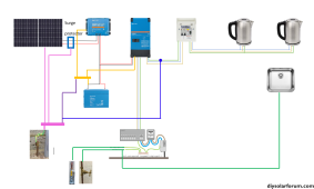
To make things clear (hopefully ?) with terminology I will try to specify words and what I mean by them first.

  • Earth or earthing connection will be a coper rod in the ground (pink in the diagram).
  • Grounding will be the negative from the DC battery (Orange in the diagram).
  • CPC (Circuit protective conductor) will be the protective cable on the AC side either the grid supply or the inverter output. Green/yellow normally (Light green in the diagram)
  • Bonding will be the water/gas and other metal parts within the building (equipotential zone) (Dark Green in the diagram)
First the system. This is a Victron Multiplus 2 running mainly on batteries but has a grid connection for either charging the batteries or supplying the inverter load when the batteries are low. There is no feed back into the grid.

I have an earth connection on all solar panels to a earth rod as shown in pink wires and a surge protector on the DC line to the MPPT. This is all to prevent build up on static and lighting induced surges.

The Victron has a neutral/CPC connection internally to provide the CPC for the AC output which is removed when grid takes over supply to prevent parallel fault paths. So, all connected appliances will have the correct fault path back to inverter for MCB and RCD operation.

My questions are:

  • Should I connect the chassis of the MPPT and inverter to the battery negative grounding the system as coloured orange in the diagram. I assume yes to protect against a DC fault to appliance chassis which will them operate the protective device (fuse).
  • Should I then connect this same grounding cable (orange) in question 1 to the earth rod to protect the appliance chassis from any static build up? Purple cable in diagram.
  • Should I connect the AC – CPC output from the inverter to the same earth rod (blue colour in diagram). Not sure about this one, does the Victron inverter have a constant AC in/out CPC connection in which as I am on a TNC-S system will this not be provided by the grid and main water gas bonding. If this was put in and a fault occurred on the grid side with fault on neutral O/C will the fault path now parallel through the inverter to earth.
  • If there is no constant CPC connection within the inverter and an earth rod connection is put in on the AC output side will this cause a potential difference hazard with other equipotential bonded parts within the house like the metal sink.
 

Attachments

  • grid rod earthing pic.png
    grid rod earthing pic.png
    222.1 KB · Views: 18
I see the words "house" and "building" in your description. So I will assume that this isn't a mobile installation.
With that being the case. Do not connect battery negative to ground.
And I assume that you already have a grid service to the house. So you already have an existing grounding system. All of the new equipment should be bonded to the existing grounding system. (One grounding system for everything)
This includes all solar equipment. (Inverter, solar panel frames and racking, metal enclosues and conduit)
Do not add any auxiliary/extra ground/earthing rods.
 
Hi Timselectric thanks for the reply you are correct this is a house installation.

Couple of things I was thinking. First, I have checked the inverter today and it does have a constant continuity between AC protective earth in and out including the case so all of the system as you have stated will be connected to the supply protective earth at all times.

I do not have an earth rob on the house, in UK we have a TNC-S where the protective earth is the neutral supply which is split when it enters the house to provide a protective multiple earth PME (I expect you may already know this ?). A PME earth is not, in general, allowed to be taken outside the equipotential zone (the house). For this reason, I am reluctant to connect the solar panels to this for static and lighting protection as the charge will go back down the supply cable and the PME will be outside the house environment. I believe in the UK it is good practise to earth the panels to a separate earth rod connected at the panel location for lighting surge and static protection. I do not have an issue with this setup.

I agree now that I do not need to connect any of the AC out to any extra earth rod as the supply provides this constant through the inverter.

As for the DC chassis connection to battery negative. If I do not connect the chassis of the inverter and the MPPT to the battery negative, then there will be no fault return path if the chassis become DC live. I have gone over the Victron manual but cannot find any reference about this. Why would it be OK to do this on a RV vehicle and not in a house. If I do not do this on the inverter then would it be good practice to connect this on the MPPT
 
I am reluctant to connect the solar panels to this for static and lighting protection
This is for electrical safety. To avoid personal injury.
A separate rod provides zero protection from personal injury. Because it's not connected to the source of the possible AC fault.
This isn't for static or lighting protection. Although, it might dissipate some static.
Lighting protection is a separate system.
As for the DC chassis connection to battery negative. If I do not connect the chassis of the inverter and the MPPT to the battery negative, then there will be no fault return path if the chassis become DC live.
You should connect the inverter chassis and all exposed metal parts.
But not the battery negative. This is only done in a mobile installation. Because the existing DC system is already done this way. And the two systems are regularly connected to each other.
In a stationary system the DC side is isolated from the AC side.
 
Ok so I will not bond the DC negative to the chassis as I cannot find any info on this either.


As for solar earth bonding to house protective conductor I was reading the guide below on page 20 to why we would not do this in UK. I thought the solar arrays are isolated from the AC side and class 2 so do not need this earth protection to main utility earth but an earth rob so the reasons I stated.

73376 Guide

I think in other countries this is a different regulation and must be connected to utility earth cable. I have looked over the IEE regs and it is not clear as this is not well covered as far as I am aware. The issue we have with taking the PME earth to the outside solar panels it can cause a hazard if an earth fault within the house occurs that does not get cleared or an open neutral to the house was to occur as the solar array will become live which will be outside the equipotential zone.

This is an interesting subject which I have been looking into for some time. Each setup has its hazards depending on the fault scenario we think up. It would be nice if I could find a definitive regulation for this installation.
 
Last edited:
If the inverter is a low frequency inverter. (transformer inside) there is some level isolation between the AC and DC sides. In a high frequency inverter. There is very little isolation (if any).
Either way , there is a possibility of a failure inside the inverter. Which can put AC voltage on the DC conductors. And if this current finds its way to the PV framework. It becomes dangerous to touch.
The purpose of grounding/ PE , is to make sure that everything remains safe to touch at all times.
 
So little more digging. The MultiPlus step up transformer is a low frequency transformer type. The primary and secondary windings are separate. This makes the DC and AC sides galvanically isolated. There should never be AC on the DC wires.

Seeing as the MPPT is also separate from the inverter and all cables and panels are class 2 then connecting the panels to the PME of the house could induce a hazard rather than protect against one.

Happy to discuss this more as its something of a hot subject.
 
If the inverter is a low frequency inverter. (transformer inside) there is some level isolation between the AC and DC sides. In a high frequency inverter. There is very little isolation (if any).
Either way , there is a possibility of a failure inside the inverter. Which can put AC voltage on the DC conductors. And if this current finds its way to the PV framework. It becomes dangerous to touch.
The purpose of grounding/ PE , is to make sure that everything remains safe to touch at all times.
I do agree with you which is why i find the UK advice at ods with other coutries. As you stated the issue will be if there was melt down on the transformer primary to secondary windings and the input AC was to get onto the DC lines, not good. I am trying to think of a good reason other than the fact it may never become live why the UK regs do not recommend this. i might post this on the IEE regs forum
 
If AC never entered the same enclosure, I would agree.
Thats a valid point I might have to rethink this. I will still try to get some clarification on the UK regs.


By bonding the solar array to the utility PME then I will not need any earthing rod

What about surge protectors would you connect these to the PME or separate earth rod
 
By bonding the solar array to the utility PME then I will not need any earthing rod
correct
What about surge protectors would you connect these to the PME or separate earth rod
The house PE, If located at the house.
At the array, I can see the argument for separate. And can't think of any reason why it would be a problem.
Personally I don't put them at the array. I'm not concerned about the solar panels. I'm only concerned about protecting the equipment in the house.
 
correct

The house PE, If located at the house.
At the array, I can see the argument for separate. And can't think of any reason why it would be a problem.
Personally I don't put them at the array. I'm not concerned about the solar panels. I'm only concerned about protecting the equipment in the house.
The surge protectors are in the house near the equipment so I can connect this to the house PE.

Done a little digging on the IET regs UK. It still unclear to the safest route for earthing solar arrays. The issue with not connecting to the house PME is as you stated if the arrays come into contact with the AC in the inverter, then the array will become live.

However, with connecting them to a PME system if there was a neutral fault to the house supply (open opt outside in the road) which I have work on a few like this, all bonding parts to the system will also become live with respect to earth. With the array outside the house this will expose a potential lethal shock risk. Either way with or without the connection there is a risk.

I am inclined to think the PME connection is the safest as an inverter fault putting AC onto the DC is more likely than an open neutral supply
 
I have posted this question on the IET UK regs forum as I do not have the up-to-date copy so will be interested in any discussion on there. In the meantime, this is a good article although a few years old about the risks with PME bonging of arrays. In the end its down to what is the most likely fault to happen.

PME solar bonding
 
Odds are, that if you lose the neutral. You will have some indication in the house. But if the panel frames are live. You would have no idea, until it's too late.
 
Back
Top