diy solar

diy solar

Busbar current carrying capacity

Solarfun4jim

Solar seduced :-)
Joined
Sep 22, 2019
Messages
743
Location
Sunny Scotland
I've noted a rule of thumb for Copper busbar current carrying capacity of 1.2*busbar width*busbar thickness in Amps.
(What is Busbar Current Carrying Capacity Calculation 5 Types of Busbar | Electrical4u)
The supplied Xuba busbars with my 280Ah cells were 15mm x 2mm, so applying formula means that these busbar might be rated close to 1.2*15*2 = 36A
Does tinning them make that much difference? These seem rather low, even if doubled up.
Anyone tested the Xuba busbars to see what they max out at (safe temp)
 
A busbar with too little cross section will get hotter. But it will still carry a lot of current (especially copper, not as much aluminum.)
A short busbar will just use the battery as a heatsink, so could get away with undersize (at the expense of its neighbor, the battery.)

Tinning has no effect on DC resistance/current carrying in the lengthwise direction. It does protect against corrosion, and could make it more compatible for contact with other metals.
Thanks Hedges, that clears that up for me. (y)
 
I want to add a comment about Busbar Installations because recently I've seen photo's of builds assembled that are very poor and the results from that will not be good.

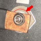
When making Busbars, CENTER the holes to the busbar !
Ensure that the "full contact surface" on the cell is in contact with the face of the busbar. Not cockeyed on an angle.

Capture.JPG<--- This isn't optimal

Either Chamfer the busbar holes or file down any ridges, edges that result from drilling out the holes.
IF using Vendor supplied Busbars also check for ridges and file them off. Most are Stamped Out and there is a slight ridge.

EVE-280AH cells, like their other models, all have a 15mm wide contact surface.
CALB I beleieve are also 15mm wide.

Always use a Busbar which, at a minimum, can cover the entire contact surface area. Verify the surface width measurement with the manufacturer's spec sheet for your cells.

You can safely use Pure Copper, 110 Copper, Tinned Copper or Nickel Plated copper bar stock.
* Nickel plated is the best for corrosion resistance without deleterious effects.
Copper Pipe can be used BUT not suggested, it IS a bodge and the results are often not as expoected. It IS a false economy.

Thanks, Back to your Regular Programming.
Steve
 
Last edited:
15 x 2 = 30 mm^2 cross section, between 2 awg and 3 awg.
Even with 90 degree insulation and bundle of 3 wires, NEC chart would put that around 100A.
Single conductor in free air, about 170A.
That's for a 60 degree C rise, from 30C ambient to 90C
 
Steve, any guidance on how far the custom bus bar should extend beyond the battery terminal? I know the terminal-to-terminal center distance, I'm not sure what the overall length of the bus bar should be.

I have aluminum bar stock on hand and was planning to use that. It's 3/8" thick and 1" wide. I'll end up with a much larger cross section than the bus bars that came with my cells.

How would I measure the efficiency of the aluminum bus bars? Can I use a standard multimeter to figure out if the old and new bus bars have similar throughput?
 
Even 4-wire ohm measurement with most bench DMM won't read milliohm levels well. I used a 5 amp power supply to measure resistance of automotive fuses, maybe 1 or 2 digits accuracy (1 to 20 milliohm.)
For a busbar, a 100A source would work better.
Looking up resistivity of the alloy and using a ruler would be more accurate. But the 3D spreading resistance from battery terminal will keep error > 1%. Good enough for your purpose.
 
As near as I can tell, the aluminum I'm using has 46% of the ampacity of the equivalent cross section of copper. My bar stock is quite a bit bigger than the cheesy bus bars that came with my batteries. Comparing one bus bar, my bar stock has more than twice the cross section.
 
Steve, any guidance on how far the custom bus bar should extend beyond the battery terminal? I know the terminal-to-terminal center distance, I'm not sure what the overall length of the bus bar should be.

I have aluminum bar stock on hand and was planning to use that. It's 3/8" thick and 1" wide. I'll end up with a much larger cross section than the bus bars that came with my cells.

How would I measure the efficiency of the aluminum bus bars? Can I use a standard multimeter to figure out if the old and new bus bars have similar throughput?
Assuming that is aimed at me.

Basically, you MUST cover the contact surface of the cell terminal. The picture above would be OK IF it was not cockeyed, that bar is long enough. Basically 2mm over and beyond the terminal faces if fine. Width isn't a big deal, so if the contact surface is 15mm and you have 25mm wide stock, no problem, again, as long as the entire contact surface on the cells make full contact with the busbar.

Lesson Learned dept: I have seen one battery pack FAIL Horribly because of a lazy assembly. My buddy was one of those "it's good enough, chuck it together & let's go" types... Did NOT pay attention, crushed some old copper pipe for busbars drilled large 3/8" holes (duh) and pluncked it together with burrs, ridges & all.... Then dimwit put 200A charger on them and wondered why two cells got so hot you physically could not touch them... He let it go and guess what... Puffed & POOFED = 100% garbage... he got lucky things did not go REALLY BAD... imagine if that had been another chemistry.... He actually blamed me for NOT forcing him to do it right ! We are NOT friends anymore, last I heard of him, he burned down the Horse Barn with a dozen horses in it... I believe he is now divorced too.... she had enough of it.
 
I think "Ampacity" doesn't mean much when a conductor is so short.
I can put about 1 amp through a 1 mil diameter wirebond (above that it burns out).
Look at the braid which connects moving contact in some power relays as an example of go way over rated "ampacity".

More important for a short bus bar are:
1) voltage drop at maximum current.
2) Watts dissipated continuously, and Joules deposited during a pulse. (which doubles if length is doubled.)

Your having double the cross section is good, cuts heat dissipation in half.
Wider and thinner, for the same cross section, will dissipate heat better (higher ampacity)
"L" or "U" shaped stock would give more area in less width.

Voltage drop is experienced by inverter, and observed by BMS.
Heat produced will be conducted into battery. Whatever temperature the battery feels like raising itself to, it will heat he busbar that much. Heat produced by the busbar will mostly go to the battery, raising its temperature and being radiated by the battery, which has more surface area than the busbar (unless in a plastic case providing thermal insulation.)

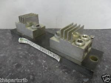
My class-T fuse holders actually have an integral heatsink:

1606764342366.png
 
Last edited:
Assuming that is aimed at me.

Basically, you MUST cover the contact surface of the cell terminal. The picture above would be OK IF it was not cockeyed, that bar is long enough. Basically 2mm over and beyond the terminal faces if fine. Width isn't a big deal, so if the contact surface is 15mm and you have 25mm wide stock, no problem, again, as long as the entire contact surface on the cells make full contact with the busbar.

Yes, that was aimed at you. I didn't think anyone else in the thread (so far) was named Steve. :)

Using your 15mm and 25mm numbers, I think I'm going to extend the end of the bus bar the same amount that the width of the bus bar extends over the terminal. I think that would put the end of the bus bar 5 mm beyond the terminal.

I may be overthinking this and perhaps the bus bar doesn't need to go beyond the terminal at all as long as it does cover the terminal.
 
You only have to cover the full terminal face. Of course you want room between busbars.
For my 280's I made some sets from 110 Copper 15mm W x 4mm thick and even with 150A charge & 200A discharge they stay cold.

Sizes for the 280AH Eves were as follows:
4.250" long for the cross bar on a Block Pack (I built my assemblies as "block" not long format.
3.750. for the regular Cell to Cell connnector
Used: COPPER C110 FLAT BAR ASTM-B133 0.125" x 0.750"

I used Brass Grub Screws on one pack and Stainless Bolts on another, no difference noted.
Similar with the 175AH packs BUT with a twist, they are simple 8S (thin but wide cells) soI ran two Aluminum Bars off the terminal to the battery cables. Connecting the Batt Cable to the Cell terminal in those packs was not a good solution IMO.

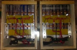
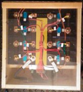
Thumbnail for 175AH packs & one of my 280AH packs. Click Thumbnail to open images up.
* These show a QNBBM-8S installed, Chargery BMS is external to box.
Yes, the boxes have Clear Tops (Optix Acrylic Sheeting 10mm thick). So much easier to peek inside LOL and hey looks cool I think.

2x-175AH-8S with QNBBM-8S.jpg 280AH-with QNBBM.jpg
 
  • Like
Reactions: Zil
Sizes for the 280AH Eves were as follows:
3.750. for the regular Cell to Cell connnector

On my EVE 280Ah cells, I measured from center of one terminal to the center of the next terminal as 2.836" or 72 mm. It was awkward getting that measurement with my digital calipers, but I did it twice to make sure. From the far edges of each terminal, the measurement is right at what you posted.

The bolts are M6. I want to minimize the diameter of the hole I put in the bus bar, but 6mm is cutting it too close. As I recall, the hole on the terminal that the bolt goes into is beveled, so the bus bar hole doesn't need to be the same size anyhow. Plus a little wiggle room in the hole is good to prevent stress on the terminal in case the cell does swell and the compression frame doesn't hold it in place. 8mm hole then?
 
Hmmm TWO SADs on my post above, I assume that is for the horses and yes I agree, these were very special show animals and a rare breed (I'm not a horse person so I don;t know all that sort of detail about breeds & such) but they had some kind of royal line or some such thing.
The bolts are M6. I want to minimize the diameter of the hole
1/4" bit works and is snug , you need a tad wiggle room, so I ended up using a 5/16 bit in my drill press. Made a wooden U shape jig and clamped it to the drill press so when I slipped the bars in they always lined up bang on and not move while drilling (bits "grab" the copper). You do need a little wiggle room, else you can very easily cross thread the aluminium and that's not good. I think 8mm is as big as I would go honestly which is just a hair bigger than 5/16.

You poor Europeans get both SAE & Metric tossed at ya ... I'm Canadian so we must know both... what a PITA !
 
Drilling aluminum, kerosene or mineral spirits make the best cutting fluid.
 
Sorry, Hedges. It just slipped out while I tried to think of something snarky for a different thread.
 
You poor Europeans get both SAE & Metric tossed at ya ... I'm Canadian so we must know both... what a PITA !
Living in the states, when I was young and in elementary school, I asked the question, "why are we learning this metric stuff". I was told, the USA is switching over to metrics. Ummmm that was more than 40yr ago... Still waiting :LOL: :ROFLMAO: The only thing I really deal with for metrics on a daily basis, is the Japanese machines I work on. LOL
 
Back
Top