


ytwytw
New Member
- Joined
- Oct 21, 2019
- Messages
- 112
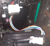
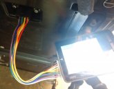
I have not received them as yet - don't expect them for at least a week. Here are photos that I asked TechDirect to provide for me before I purchased.
View attachment 5019View attachment 5020
This looks really nice and they are on wheels too, how much did you paid in total? how much for shipping?


.png")


")
.jpg")
.png")

