The first thing to do is connect to Bluetooth.
If you only have one, then skip this:
- Scroll down until you get to "Bluetooth MAC Address"
- Change it to anything "1 - 65535"
On the MainView tab press "FE-LI Param", it doesn't really matter, but it made me feel like I did something important.
Pres Param1 tab.
Put in the settings, 1 by 1.
- You have to press SET after every item you change. I press SAVE also. (Again, I don't know if SAVE actually does anything, but it made me happy)
Here are my "safest" settings I can think of:
View attachment 8303View attachment 8302View attachment 8301View attachment 8300
(High Res Screen Shots)
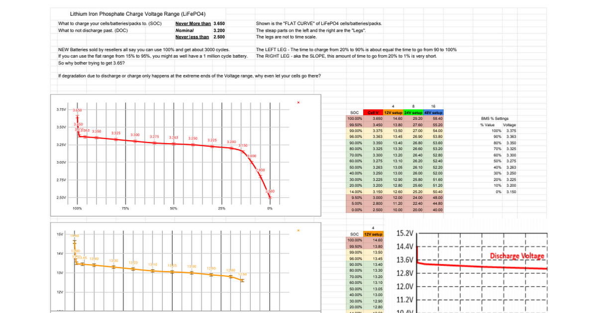
I am basing these settings off of using the flat part of the LiFEPO4 discharge curve. Feel free to experiment though. My settings stay in the flat 80%, and avoid the legs.
Sheet5 Lithium Iron Phosphate Charge Voltage Range (LiFePO4) What to charge your cells/batteries/packs to. (SOC),Never More than,3.650,Shown is the "FLAT CURVE" of LiFePO4 cells/batteries/packs. What to not discharge past. (DOC),Nominal,3.200,The steap parts on the left and the right are the "Le...

docs.google.com


.png")
.png")
.png")

")


