


You are using an out of date browser. It may not display this or other websites correctly.
You should upgrade or use an alternative browser.
You should upgrade or use an alternative browser.
BYD BMS
- Thread starter jasonhc73
- Start date
jasonhc73
Cat herder, and dog toy tosser.
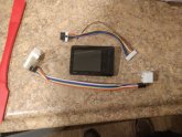
Rewired...

Now I can BMS without worrying one killing it all.
 drive.google.com
drive.google.com
drive.google.com
Now I can BMS without worrying one killing it all.
20200216_131605.mp4
drive.google.com
20200216_131206.mp4
drive.google.com
Thanks for the diagrams. However, can you check the TE numbering? I find cells 1,2 on pins 7,23. Seems flipped. Pin 8 is batt neg.Minor update.
The wires I ordered got lost in the mail. I ordered some more and should be here in 3 or 4 days.
And this drawing I am finishing up...
View attachment 5326
High Res Drawing.
The other pictures.
View attachment 5933
View attachment 5934 View attachment 5935
View attachment 5936 View attachment 5937
View attachment 5938 View attachment 5939
jasonhc73
Cat herder, and dog toy tosser.
It very well could be for the pack you have. There are at least 3 versions of these BYD packs.Thanks for the diagrams. However, can you check the TE numbering? I find cells 1,2 on pins 7,23. Seems flipped. Pin 8 is batt neg.
How did you check the voltage?
I made a similar wiring harness using a TE header to jst to a batteryGo BG-8S. I have 6 packs and they all have this wiring pattern.
Three different batt versions would make it tricky to make a generic wiring adapter. Are there pack identifying markers?
Three different batt versions would make it tricky to make a generic wiring adapter. Are there pack identifying markers?
jasonhc73
Cat herder, and dog toy tosser.
I didn't notice any difference in the outside. I only noticed when I was checking/verifying continuity. Only 1 of my 8 packs was different. If you do the inside with the F/F breadboard jumpers then it's a simple fix.I made a similar wiring harness using a TE header to jst to a batteryGo BG-8S. I have 6 packs and they all have this wiring pattern.
Three different batt versions would make it tricky to make a generic wiring adapter. Are there pack identifying markers?
Attachments
fatheryepp
New Member
- Joined
- Feb 21, 2020
- Messages
- 2
I just got the ant BMS, do you the default settings or is there a special config required for the BYD batteries?
I didn't notice any difference in the outside. I only noticed when I was checking/verifying continuity. Only 1 of my 8 packs was different. If you do the inside with the F/F breadboard jumpers then it's a simple fix.
jasonhc73
Cat herder, and dog toy tosser.
The first thing to do is connect to Bluetooth.I just got the ant BMS, do you the default settings or is there a special config required for the BYD batteries?
If you only have one, then skip this:
- Scroll down until you get to "Bluetooth MAC Address"
- Change it to anything "1 - 65535"
Pres Param1 tab.
Put in the settings, 1 by 1.
- You have to press SET after every item you change. I press SAVE also. (Again, I don't know if SAVE actually does anything, but it made me happy)

.png")
.png")
.png")
(High Res Screen Shots)
I am basing these settings off of using the flat part of the LiFEPO4 discharge curve. Feel free to experiment though. My settings stay in the flat 80%, and avoid the legs.

Lithium Iron Phosphave Charge Range
Sheet5 Lithium Iron Phosphate Charge Voltage Range (LiFePO4) What to charge your cells/batteries/packs to. (SOC),Never More than,3.650,Shown is the "FLAT CURVE" of LiFePO4 cells/batteries/packs. What to not discharge past. (DOC),Nominal,3.200,The steap parts on the left and the right are the "Le...
Last edited:
fatheryepp
New Member
- Joined
- Feb 21, 2020
- Messages
- 2
Thank you for this information. Highest charge i was able to get on my pack was 27v, then i let it sit and it settled at 26.7v.
The first thing to do is connect to Bluetooth.
If you only have one, then skip this:
On the MainView tab press "FE-LI Param", it doesn't really matter, but it made me feel like I did something important.
- Scroll down until you get to "Bluetooth MAC Address"
- Change it to anything "1 - 65535"
Pres Param1 tab.
Put in the settings, 1 by 1.
Here are my "safest" settings I can think of:
- You have to press SET after every item you change. I press SAVE also. (Again, I don't know if SAVE actually does anything, but it made me happy)
View attachment 8303View attachment 8302View attachment 8301View attachment 8300
(High Res Screen Shots)
I am basing these settings off of using the flat part of the LiFEPO4 discharge curve. Feel free to experiment though. My settings stay in the flat 80%, and avoid the legs.
Lithium Iron Phosphave Charge Range
Sheet5 Lithium Iron Phosphate Charge Voltage Range (LiFePO4) What to charge your cells/batteries/packs to. (SOC),Never More than,3.650,Shown is the "FLAT CURVE" of LiFePO4 cells/batteries/packs. What to not discharge past. (DOC),Nominal,3.200,The steap parts on the left and the right are the "Le...docs.google.com
jasonhc73
Cat herder, and dog toy tosser.
That's 99% according to the slope chart. Sounds great to me! 26.7V is somewhere between 85% and 90%, which is fantastic also! ?Thank you for this information. Highest charge i was able to get on my pack was 27v, then i let it sit and it settled at 26.7v.
There is no magic SOC direct absolute chart. It's all just a "fuzzy suggestion".
If you really want to do a full-on absolute measurement, you have to have a Columb meter and put a very fixed load on and then just record everything, volt/amp/IR/temperature/humidity/wire size/wire length/power factor/insulation.
And even then, it's still just a "model", which only applies to that load and conditions. The real world is never the model.
I didn't notice any difference in the outside. I only noticed when I was checking/verifying continuity. Only 1 of my 8 packs was different. If you do the inside with the F/F breadboard jumpers then it's a simple fix.
I sketched up these adapter boards. Two balance connectors for each of the two flavors. J1/J2 are the TE connectors. J3/4 have cell1 on pin7. J5/6 have cell1 on pin4. Populate the ones you need.
I'll size traces, fill planes, and move things around a bit before sending out to fab. Thoughts anyone?

Traces looks a bit thin for balancing current (I guess that's 10 or 12 mils, I'd use 50 mils if possible, or at least 25 mils if you can't). Looks great otherwise")


External traces, @.38mm(15.15mil), 2oz, no via's. Vendor calculator gets ~1.5A. My Chargery is a 1.2A balancer.
Trying to accommodate 2 battery config's is not optimal. I may just end up making adjacent board layouts and snap it post build.
I also have an active balancer @5A.. this would be interesting to make a separate board for that with screw headers.
Last edited:
You're wasting a lot of board space by not placing H1 and H2 side by side, you should try that
Oh that's 2 oz, you're fine then
NB: the standard is 1 oz, I hope you're not paying any extra for the 2 oz because in this case you should just go for 1 oz with bigger traces (20 mils / 0.50 mm will give only a 11 °C rise at 1.5 A so that would be fine but I'd put 25 mils or more to be safe).
External traces, @.38mm(15.15mil), 2oz, no via's. Vendor calculator gets ~1.5A. My Chargery is a 1.2A balancer.
Oh that's 2 oz, you're fine then
NB: the standard is 1 oz, I hope you're not paying any extra for the 2 oz because in this case you should just go for 1 oz with bigger traces (20 mils / 0.50 mm will give only a 11 °C rise at 1.5 A so that would be fine but I'd put 25 mils or more to be safe).
You're wasting a lot of board space by not placing H1 and H2 side by side, you should try that
Oh that's 2 oz, you're fine then
NB: the standard is 1 oz, I hope you're not paying any extra for the 2 oz because in this case you should just go for 1 oz with bigger traces (20 mils / 0.50 mm will give only a 11 °C rise at 1.5 A so that would be fine but I'd put 25 mils or more to be safe).
Bam! 2A, .58 mm

jasonhc73
Cat herder, and dog toy tosser.
Bam! 2A, .58 mm
View attachment 8473
[/Q
Keep in mind, 24 AWG is good for 3.5 amps (0.20mm²). 0.58mm looks like can handle about 7 amps. (https://www.engineeringtoolbox.com/wire-gauges-d_419.html)Traces looks a bit thin for balancing current (I guess that's 10 or 12 mils, I'd use 50 mils if possible, or at least 25 mils if you can't). Looks great otherwise
My ANT-BMS only does 0.200 amp. The BMS doesn't transfer current, it just shorts out the top cell with a small resistive load.
jasonhc73
Cat herder, and dog toy tosser.
OK, I see 5 inputs and 1 output. Right?View attachment 8468View attachment 8469
External traces, @.38mm(15.15mil), 2oz, no via's. Vendor calculator gets ~1.5A. My Chargery is a 1.2A balancer.
Trying to accommodate 2 battery config's is not optimal. I may just end up making adjacent board layouts and snap it post build.
I also have an active balancer @5A.. this would be interesting to make a separate board for that with screw headers.
Consider the 32pin the output, and everything else as an input.
The 12pin TE connects directly to the 10pin Molex.
The left 2 pins on the Molex are for the 24V Fan. The other 8 pins can be anything, I just made them 1-8 cells.
I like the JST-XH 9 pin headers.
If you skip using the Molex connector (that is where there randomness has happened), Then really you only need the 12pin TE and the 9 pin JST-XH headers, right?
Last edited:
Very nice ?
Okay.. engineers can't help but optimize. This is as small as it gets. I forgot to bump out to make a mounting hole.

jasonhc73
Cat herder, and dog toy tosser.
I think just 1 9 pin connector is fine. You can rearrange the wires on the ribbon cable pretty easy.Okay.. engineers can't help but optimize. This is as small as it gets. I forgot to bump out to make a mounting hole.
View attachment 8492
OK, I see 5 inputs and 1 output. Right?
Consider the 32pin the output, and everything else as an input.
The 12pin TE connects directly to the 10pin Molex.
The left 2 pins on the Molex are for the 24V Fan. The other 8 pins can be anything, I just made them 1-8 cells.
I like the JST-XH 9 pin headers.
If you skip using the Molex connector (that is where there randomness has happened), Then really you only need the 12pin TE and the 9 pin JST-XH headers, right?
I see it the other way. 32p input to 5 outputs. One to the 12p TE header (presumably to connect to the molex for a “no cut”) and two pairs of JSTs (to account for the differing wiring in the 32p). During testing I want a bms on the modules and then wanted an option to connect another something. It’s a universal board that’s hopefully handy for others coming up this ramp.
jasonhc73
Cat herder, and dog toy tosser.
The only spot I had different wiring was on the 10 wire Molex. The 32p TE is the same on all 8 of my packs.I see it the other way. 32p input to 5 outputs. One to the 12p TE header (presumably to connect to the molex for a “no cut”) and two pairs of JSTs (to account for the differing wiring in the 32p). During testing I want a bms on the modules and then wanted an option to connect another something. It’s a universal board that’s hopefully handy for others coming up this ramp.
An awesome idea having another type of "something"... Maybe a high amp balancer!
Okay.. engineers can't help but optimize. This is as small as it gets. I forgot to bump out to make a mounting hole.
View attachment 8492
Even nicer ?
The only spot I had different wiring was on the 10 wire Molex. The 32p TE is the same on all 8 of my packs.
An awesome idea having another type of "something"... Maybe a high amp balancer!
I want to get these two into the mix during setup. The left balancer can pull 5.5A. This won’t be going through the JST. The pack differential was < ~200mA so hopefully they will stay in that range.
