diy solar

diy solar

cable size?? fuse size??

johnskdyvn

New Member
Joined
Nov 8, 2021
Messages
53
I've watched so many videos on how to setup a Growatt 3000 system, but the one thing i can never seem to find is what cable and fuse sizes i need to use? I bought a 3000w Growatt inverter, (4)SOK batteries (12v x 206ah), and I have 3600 watt solar panel array (12 x 300w panels). While connecting my batteries in series to make a 48v system, what size cables should connect the batteries together? 2/0 vs 2 vs 1? Also, where should i use a fuse (between the battery and the inverter)? What size fuse? What kind of fuse? Will Prowse uses the rack type battery system now in his videos so there is no need to add in a fuse in his videos. I already have my (4) batteries bought and paid for. I just can't seem to find the answers anywhere. I am NOT that electrically inclined. I want to make sure the whole system is set up correctly without burning down my off-grid cabin. Thanks so much for any and all opinions on this.
Johnny
 
I've watched so many videos on how to setup a Growatt 3000 system, but the one thing i can never seem to find is what cable and fuse sizes i need to use?
3000 ac watts / .85 conversion factor / 48 volts low cutoff = 73.529411765 service amps
73.529411765 service amps / .8 fuse headroom = 91.911764706 fault amps

That means pure copper 6 awg wire with 105C insulation and a 100 amp fuse minimum.
Better to go with 4 awg and a 150 amp fuse.
The wires may even need to be thicker if the round trip circuit length is significant?
how far is the Growatt going to be from the batteries?
I bought a 3000w Growatt inverter, (4)SOK batteries (12v x 206ah), and I have 3600 watt solar panel array (12 x 300w panels). While connecting my batteries in series to make a 48v system, what size cables should connect the batteries together? 2/0 vs 2 vs 1?
All the current flows through each battery in a chain so the interconnections between the batteries need to be the same gauge as the overall circuit. So 6 awg minimum for the interconnects, 4 awg preferred.
Also, where should i use a fuse (between the battery and the inverter)?
You should have a class t fuse right at the battery positive terminal.
The closer the better to minimize the chance of a short upstream of the fuse.
If you will have more circuits than just the growatt you should use a fused busbar on the positive side and a unfused busbar on the negative side.
This makes for an orthodox system that makes sense at a glance.
More importantly it enforces a feeder branch topology where each of the branch circuits are fuse protected at their source.
This is good because it allows for the possibility of isolating faults to a branch circuit.
This is a good fused busbar for smaller applications like yours.
This is a good un-fused busbar for the negativbe side in your application.
What size fuse?
answered above
What kind of fuse?
mrbf for the branches and class t for the battery.

In this case you might go for a 125 amp fuse on the inverter branch and 150 amp for the class t.
This way the cheaper fuse has a chance to blow first as the class t fuses are expensive.
That is only possible with 4 awg wire.
 
Hello - It's difficult to use a generic cable and fuse size since each installation and required cable length and laods are all different. Since you're using a 48 volt system your wire will be substantially smaller than a 12 volt system since 48 volts has only 25% the current of 12 volts.

Regards - Mike
 
Thank you so much for your reply. Would these be adequate for connecting the 4 SOK batteries into series?
Thanks again.

 
Thank you so much for your reply. Would these be adequate for connecting the 4 SOK batteries into series?
Thanks again.

Those cables have 5/16" lugs(~8mm), what size are the studs on the sok battery?
Common sizes are 1/4"(6mm), 5/16"(8mm) and 3/8"(10mm).

Those cables say OFC=oxygen free copper which worries me.
They don't say the temperature the insulation is rated for which worries me even more.
 
Those cables have 5/16" lugs(~8mm), what size are the lugs on the sok battery?
Common sizes are 1/4"(6mm), 5/16"(8mm) and 3/8"(10mm).

Those cables say OFC=oxygen free copper which worries me.
They don't say the temperature the insulation is rated for which worries me even more.
The SOK batteries have 5/16' lugs. My hope is to get everything i need for this system, but then to have a second set of more experienced eyes help me set it up.
 
My hope is to get everything i need for this system, but then to have a second set of more experienced eyes help me set it up.
A cheaper and likely less frustrating approach is to fully design the system first, post a full schematic for review, and then only buy parts once all issues in the design are resolved.
 
A cheaper and likely less frustrating approach is to fully design the system first, post a full schematic for review, and then only buy parts once all issues in the design are resolved.
Thank you rmaddy. The issue is i'm having a difficult time drawing a schematic when i have no idea where the fuses are supposed to go, let alone the size of cables i'm supposed to use. If i could afford a new rack system type of battery it looks like it would solve most of my issues, unfortunately, i already purchased those SOK batteries. I can build stuff all day with wood, but when it comes to electricity i error tremendously on the side of caution.
 
Thank you rmaddy. The issue is i'm having a difficult time drawing a schematic when i have no idea where the fuses are supposed to go, let alone the size of cables i'm supposed to use. If i could afford a new rack system type of battery it looks like it would solve most of my issues, unfortunately, i already purchased those SOK batteries. I can build stuff all day with wood, but when it comes to electricity i error tremendously on the side of caution.
Start with a rough diagram showing what you have and what you think is right. People here can help you work out the details to get everything right.
 
If you have not built the system yet, in your list of things to buy, I’d get something like:

a Crimper:
I have used an older version.


b. Heavy Duty Wire Cutter:
I use this

C. And some heat shrink:
I linked the 1/2 inch stuff I have used, but not sure what size will fit your wire.

D: Lugs
I have used a different sizes of these and they are UL listed.

I found making cable easy, but measuring cable length accurately not so easy.
 
Last edited:
So far we know you have a growatt all_in_one and 4 batteries?
Will you have any other loads or charge sources?
If not the topology is really simple.
Like this...
Code:
battery.positive<->class_t_fuse<->growatt<-double_pole_single_throw_breaker<-panels.positive
battery.negative<---------------->growatt->double_pole_single_throw_breaker->panels.negative
 
Last edited:
Only slightly more complicated with a shunt, busbars and earth ground.
Code:
legend {
    {} { functional block }
    nnn|NNN| { fused busbar position where nnn is the wire guage and NNN is the fuse rating in amps }
    nnn|UUU| { un-fused busbar position where nnn is the wire guage }
    <-> { bi-directional current flow }
    -> { uni-directional current flow }
    <- { uni-directional current flow }
}
main {
    positive_busbar {
        004|UUU|<->class_t_fuse<->battery.positive
        004|125|<->growatt.positive<-dpst_breaker<-panels.positive
        016|001|->shunt.positive
    }
    negative_busbar {
        004|UUU|<->shunt<->battery.negative
        004|UUU|<->growatt.negative->dpst_breaker->panels.negative
        006|UUU|<->growatt.equipement_ground
        006|UUU|<->premesis_ground
    }
}
 
Last edited:
So far we know you have a growatt all_in_one and 4 batteries?
Will you have any other loads or charge sources?
If not the topology is really simple.
Like this...
Code:
battery.positive<->class_t_fuse<->growatt<-double_pole_single_throw_breaker<-panels.positive
battery.negative<---------------->growatt->double_pole_single_throw_breaker->panels.negative
My loads will be very simple for this 400 sq foot cabin. 2 wall lights, (1) 10 cu foot chest freezer, laptop, phone charger, and i'll be running a window AC unit during the summer months. Everything combined should be 2000 watts or less. The cabin is mostly bare bones and i'm just looking at enough electricity to function in. Right now, i'm using a 2kw honda inverter generator and that is plenty enough electric to power everything that i listed.
 
My loads will be very simple for this 400 sq foot cabin. 2 wall lights, (1) 10 cu foot chest freezer, laptop, phone charger, and i'll be running a window AC unit during the summer months. Everything combined should be 2000 watts or less. The cabin is mostly bare bones and i'm just looking at enough electricity to function in. Right now, i'm using a 2kw honda inverter generator and that is plenty enough electric to power everything that i listed.

Sounds like all your loads are AC and no other charge sources are planned so your topology is very simple.
I suggest you use the busbars pattern I sketched above.
 
3000 ac watts / .85 conversion factor / 48 volts low cutoff = 73.529411765 service amps
73.529411765 service amps / .8 fuse headroom = 91.911764706 fault amps

That means pure copper 6 awg wire with 105C insulation and a 100 amp fuse minimum.
Better to go with 4 awg and a 150 amp fuse.
The wires may even need to be thicker if the round trip circuit length is significant?
how far is the Growatt going to be from the batteries?

All the current flows through each battery in a chain so the interconnections between the batteries need to be the same gauge as the overall circuit. So 6 awg minimum for the interconnects, 4 awg preferred.

You should have a class t fuse right at the battery positive terminal.
The closer the better to minimize the chance of a short upstream of the fuse.
If you will have more circuits than just the growatt you should use a fused busbar on the positive side and a unfused busbar on the negative side.
This makes for an orthodox system that makes sense at a glance.
More importantly it enforces a feeder branch topology where each of the branch circuits are fuse protected at their source.
This is good because it allows for the possibility of isolating faults to a branch circuit.
This is a good fused busbar for smaller applications like yours.
This is a good un-fused busbar for the negativbe side in your application.

answered above

mrbf for the branches and class t for the battery.

In this case you might go for a 125 amp fuse on the inverter branch and 150 amp for the class t.
This way the cheaper fuse has a chance to blow first as the class t fuses are expensive.
That is only possible with 4 awg wire.
Hi, I am learning here that I want to redo my battery cabling, (right size 2/0 but poor quality lugs) and my main battery fuse. Based on the formula I see you using, I should go with a probably 500 amp T fuse. Does this sound correct? Inverters, 7000 ac watts, /.85/24volt=364.58/.8=455.72. that would also fit the amps of the bank ( each batt@ 50x10 ea. )
 
Hi, I am learning here that I want to redo my battery cabling, (right size 2/0 but poor quality lugs) and my main battery fuse. Based on the formula I see you using, I should go with a probably 500 amp T fuse. Does this sound correct? Inverters, 7000 ac watts, /.85/24volt=364.58/.8=455.72. that would also fit the amps of the bank ( each batt@ 50x10 ea. )
7000 continuous watts is big for 24 volts.
Is it too late to go 48 volts?

For 455 amps you will need 2*2/0 awg each with a 300 amp fuse.
Then we need to consider voltage drop.
What is the round trip length between the inverter and the batteries.

What does "50x10 ea." mean?
Perhaps including some units of measure might help.
 
Sorry, the battery system is 10 each BB5024, (Battle born 24 volt 50 AH) cabled to maintain 24 volts I started with 24 volt system before 48 became standard. and as each component needed replacing the others influenced staying on the 24 volt system. I would love to switch to 48 but my dual Outback inverter system is 24 volts only, and 5 years only. (Outback Flexpower two using two VFX 3524a inverters). So continuous output is up to 7000 ? I would have to buy new inverters. The batteries could easily be rewired, but it would be quite a cost to replace the inverters, and the Mate 3s, the Flexnet battery monitor , shunts etc. Todays equivalent is just under 8K. I have toyed with the idea of putting the Flexpower2 on ebay and going with a more modern system.
Round trip from farthest battery to master inverter is 20 feet.
Thank you for your answer.
For 20 feet round trip you should have double 2/0 awg from batteries to busbars each with 300 amp class t fuse.
From busbars to each inverter gets 2/0 awg with a 300 amp fuse.
 
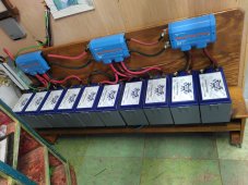
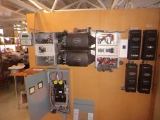
wow I am so not like that, my application is off grid dwelling these are while I was working on the setup, its all covered and tidied up now, the messy wiring is the way it came, I have tidied that also, and the charge controllers have been changed. Sorry I am abroad and do not have current pics.
 

Attachments

  • 10 batteries.jpg
    10 batteries.jpg
    261.3 KB · Views: 22
  • DSC01270.JPG
    DSC01270.JPG
    636.8 KB · Views: 22

diy solar

diy solar
Back
Top