diy solar

diy solar

Battery fuse size without an inverter

Sparks-n-Splinters

New Member
Joined
Jan 2, 2024
Messages
69
Location
Rest Stop, IA
Hey folks!
Ive been scouring the boards and watching Will's videos as I begin to plan and assemble a small (as Will's site puts it) a minimalist set up. After weeks of off grid camping the wife and I have dialed down out power needs and have decided to drop the inverter. That being said, every bit of info I find on sizing a MRBF for the batteries seems to be based off the inverter size.

Ive got 2- Li Time 12v 100ah lifepo4 batteries which state max. continuous discharge is 100A

Those 2 will be in parallel so a 200A fuse? The DC fuse block is only rated for 100A

Did a miss a formula somewhere?

One last question as this is my first time playing with lithium batteries The instruction manual shows using buss bars for 2 batteries in parallel and I was not expecting that. So how do I figure the amp rating for the bars?

Many thanks in advance.
 
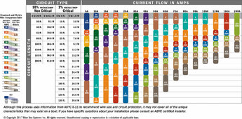
Overcurrent protection devices are sized based on the device or wire gauge with the lowest current rating. DC fuse block is 100A so a 100A fuse is called for unless the wiring is too small then the fuse is selected on the ampacity chart for that gauge of wire.

What is the total off all your DC loads?
 
Questions from someone with possibly only slightly more experience:
1. Are your devices wired directly to the battery, or is the battery going to an existing fuse block?
2. How are you distributing power?
3. How are you planning to connect/disconnect from the battery?

Inquiring minds and all that...
I'm pretty much following Will's video for the minimalist set up

All my devices will be through 12v plug (cig lighter type) and USB outlets that are wired to the fuse block.

I made a couple upgrades- an xt60 plug and breaker to disconnect the PV panels, and a battery monitor, and my SCC is the Victron 100/20

As of yet I have not chosen a battery disconnect switch.

Almost all the parts are here, should be starting the build later this week.
 
Ok, I missed something. Bluesea MRBF fuses are sold with ampacities of greater then 100 amp for their fuse holders. I'm using 125 amp fuses one for each battery. Also set up a 300 amp MRBF to feed wiring to the inverter.
 
Ok, I missed something. Bluesea MRBF fuses are sold with ampacities of greater then 100 amp for their fuse holders. I'm using 125 amp fuses one for each battery. Also set up a 300 amp MRBF to feed wiring to the inverter.
I think your right. I missed multiplying by 125%. Or was that only for inverter loads?:unsure:
 
Fit 100A MRBF to each battery, to protect against worst case, one battery could fail and the other dump its energy into it.
With cable rated for 100 amps connect from each fuse to a buss bar. From buss bar to fuse distribution, fit a link fuse suitable for expected loads, example 40A. From buss bar to solar controller fit a fuse 30A.
To get good sized studs / nuts suggest a 200 amp buss bar.
Link fuses as close as practical to the buss bar.
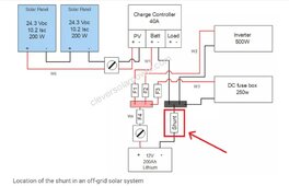
Example simple system, shunt is optional. Error in diagram, main battery fuse before isolator, not after as shown.
Screenshot_20230905-200359_Chrome~2.jpg
 
@MisterSandals - According to Wills page the battery to fuse block wire is 4AWG. The fuse block is rated overall at 100A, and the battery is 100A max continuous.
Removing the inverter and only running DC loads has confused me a bit. Do I still need to multiply by 125% or go with the max DC rating?
 
Back
Top