diy solar

diy solar

Calculation of parallel string battery currents

Thank you for this. The entire time I thought the lower battery resistance would help keep the battery load balanced. Of course that is flat wrong.

This actually says with LFP or similar low resistance batteries the balanced connection is more important than ever.
That article I referenced with calculations made 32 years ago set the battery IR at 20 milliohms; really? The LFP batteries everyone on this forum are using have IR typically less than 1 milliohm, and those numbers I posted for the 1/2 milliohm IR in various hookups like Example 6 are terrible. You can't get cable and lugs big enough to balance that which wouldn't be too big to fit on a battery terminal; I think bus bars are a must especially since these modern setups are often pulling multiple 100's of amps, and may very well overheat a cable with lugs small enough to fit on a big LFP battery.
 
Last edited:
Wherever this ends up I think this thread and the spin off that contains the math is ’pin worthy.’ I have had the smart gauge parallel battery in my signature block for a year and would love to see the math behind it.

IMO, the math portion could get posted in the resource section, perhaps in the planning and sizing subsection. https://diysolarforum.com/resources/categories/planning-and-sizing-tools.5/

the downloadable pdf file would not have the content lost in pages of back and forth as threads sometimes do.
I remember studying something like this in my EET courses at DeVry:
nodal analysis
 
I don’t have a real imeadance measrement device for my batteries like a yr1035+, but I do have a milliohm reading on my batteries as I do a capacity check. Ican’t speak to the accuracy, but the internal resistance is significantly more empty than full, and it builds resistance quickly. On my 25 ah cells, they started with 1 - 4 milli ohms, but went up to 25 to 45 milliohms. I would think if resistance goes up as batteries drain, it would make them a bit more balanced than the lower resistance math shows.
Quite true. Conversely, as the batteries are being charged, the IR will go down leading to worse balance.

The remarkable property of these new connections I've discovered is that the balance doesn't change when the IR changes, as long as all the batteries' IR tracks under all conditions, temperature, SOC, etc.
 
The 1 kHz impedance measurement only represents a smaller portion of cell terminal voltage slump. Overvoltage slump dominates at most used range of load current. 1 kHz impedance is mostly conductive resistance of cell metallic connections within cell, with a minor amount of ionic diffusion resistance.

Cell 1kHz impedance cell terminal voltage slump has an almost linear relation to cell current.

Overvoltage slump, also called polarization potential, is overhead energy used by cell to move lithium ions within cell to supply demanded current. Its terminal voltage variance value has a logarithmic relation to cell current. It is highly dependent on aging of cell and cell temperature.

As cell ages, overpotential slump will degrade 3x or more from its initial new cell overpotential value for moderate, 0.2-0.4 C(A) cell demand current. Overpotential cell terminal voltage slump at moderate cell current correlates well to cell matching and extractable capacity. It has an exponential time constant decay to equilibrium. In the 15% to 90% state of charge range for LFP, the time to equilibrium terminal voltage is in the 1 to 3 minute range. For given model cell, it is dominate effect for cell matching. 1 kHz impedance measurement is not a good indicator of cell matching.

Overvoltage slump is highly dependent on cell temperature. It rises at a greater rate below about +10 degrees C. This is why LFP performance drops off significantly at cold temps.

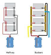
Many folks have trouble with bus bar connection resistance due to aluminum oxide build up on cell terminals. Clean terminals with solution of 50% - 70% water diluted white vinegar to remove oxide then clean then dry with 91-99% isopropyl alcohol. Aluminum oxide regrows quickly so terminal connections need to be clamped down soon after cleaned and dried. Keep salty fingers off of contact surfaces.

FYI, the slight bumps in SoC voltage curve is due to the way lithium ions are stored in the negative electrode graphite lattice layers. The lattice layers are like a multi-level parking garage that only opens particular levels when previous parking level is nearly full. The most prominent bumps are at about 55% and 10% state of charge points where a new parking level arrangement happens. There are four other minor bumps that are harder to detect by SoC open circuit voltage.

For LFP cells, the overall cell voltage is the positive LFP cathode electrode potential minus the negative graphite electrode potential. LFP cathode has a very flat voltage versus SoC until less than about 5% state of charge. Most of the SoC voltage profile is due to graphite negative electrode which ranges from about -0.25 vdc at totally discharged to about 0 volts at fully charged. LFP positive electrode potential is almost flat at 3.43 vdc from fully charge to about 5% state of charge where it starts to quickly collapse. This means fully charged cell is close to 3.43vdc rested open circuit voltage.

Cell open circuit voltage when absorb charged above 3.43v is due to surface charge, mostly in graphite. This has very little capacitance storage capacity, approximately 0.01% of cell AH capacity, and can be quickly dissipated with a short load. 0.01% of 280 AH cell is only 28 mAH's. This surface charge will bleed off on its own if cell is left open circuited in a few hours to a few days. Don't think because your top balanced cells have rested open circuit voltage between 3.45v and 3.65v they are not balanced. As long as their rested open circuit voltage stays above 3.45v they are full charged and balanced.


LF280 AH battery dischg 0.1C-1.0C.png
Good battery connecitons.png

LFP Over-potential Chart.png

Li-Ion Graphite battery model.jpg
 
Last edited:
Here is a comparison of two hookups of 4 batteries in parallel, with an image from Victron to illustrate:

batt6-png.90481


The hookup on the left is the well-known "Halfway" connection which gives theoretical perfect balance. It depends on the IR of the 4 batteries remaining identical, and, of course, in the real world those parameters will not perfectly track. If the batteries are nominally identical, same manufacture date, etc., even if there is some lack of equality of battery IR the balance will be good.

The hookup on the right using busbars with the usual connection of the load (red and black cables) to the extreme corners can have good, but never theoretically perfect balance. If the connection is modified slightly as shown by the yellow and blue cables, the balance becomes theoretically perfect, with the requirement that the IR of the 4 batteries track. A particular advantage of the yellow/blue connection is that the balance does not require the busbar resistance to be very low (but it shouldn't be high enough to cause the busbar to overheat).

To change the usual connection as shown by the red and black to the yellow and blue connection is trivially easy. To implement the "Halfway" hookup with busbars will not be as easy. The choice seems slanted toward the busbar and yellow/blue hookup.
 

Attachments

  • Batt6.png
    Batt6.png
    32.4 KB · Views: 388
Last edited:
I would be curious to how much variation is tolerable. And at what point should adjustments be made or verifying connections.
 
I see the numbers of the out of balance configurations to be maybe 3+ amps out of 30 or roughly 10%.
If it is wired right should it be within 2%? Say a 200 amp load and the four are all 48 to 52 amps do we say that is fine. Or should they be within 1 amp or start looking for an issue. Or 100 mA?

This is the whole theory vs practice thing.

I have two in parallel and a heavy draw might 68 and 75 amps. Inverter comes off one end of a short bus with four terminals and each battery is connected to one of the middle studs. Wire is very close to same length. I think I want to review mine again.
 
I see the numbers of the out of balance configurations to be maybe 3+ amps out of 30 or roughly 10%.
Are you referring to one of the calculated Examples? If so, cite which one. In post #3 I gave 3 examples of the calculated out of balance for 3 different values of battery IR. Could you be more specific please. I could do a special calculation if you can give the battery IR and link resistance.
 
Perhaps you're asking about sensitivity to a failure of all the battery IR's to track. Let me run an example. Set the battery IR's to 1 milliohm, typical for a somewhat high IR of modern LFP batteries, set the link resistance to 1 milliohm, higher than what a good busbar setup would give you. Then using the 4 battery parallel hookup with a diagonal connection, I calculate these currents in amps:

Example 16
37.5
12.5
12.5
37.5

Now if the link resistance is set to 1/10 milliohm (this is busbar range), the currents become

Example 17
27.3
22.7
22.7
27.3

But let's see what happens with my change to the connection load as given by the yellow and blue in post #26. The battery IR is still 1 milliohm except set the IR of battery 3 to 1.1 milliohms--a 10% increase, and link resistance set back to 1 milliohm. The currents are now:

Example 18
25.1
25.4
24.0
25.5

This is still very good. To get balance not even this good with the red and black connection in post #26, we had to decrease the link resistance from 1 milliohm to 1/10 milliohm. So a 10% increase in one batteries' IR caused a fairly small increase of imbalance. Compare to the imbalance of the standard diagonal connection even when the battery IR of all the batteries matched. To get better balance, but not even as good as Example 17 we had to decrease the link resistance to 1/10 milliohm; this is the range you could get with thick busbars. The yellow/blue connection was better than this even with a 10% mismatch in the IR of one of the batteries, and with link resistance much higher than you'd get with thick busbars.
 
Yes #16 something needs fixed, #17 still something wrong, #18 would seem tolerable with maximum 4% (1/25).
My thought was to work backward from the actual battery current measurements to find the issue and how much is tolerable.
Nothing I can do to change the cells or battery IR. Just to look at cable length, connections and placement.
 
I said in the beginning I didn't want this thread to be a propellor head thread. The community is not all EE's and I don't want to scare anyone away from reading this thread all the way through.
GRATS on making it this far before my pedanticism. Start a "Math for Smarties" thread?
 
How about for the semi-common 6 packs of Gyll batteries in parallel config?
 
What would be the typical IR for the batteries, and the resistance of the busbars between two adjacent batteries?
A good bus bar to terminal surface clamping interface resistance is 0.04 to 0.08 milliohm. Poor terminal connection can be much greater. Making low resistance cell terminal connections is one of the common issues with DIY'er construction. Aluminum cell terminals quickly grow aluminum oxide surface coating which is non-conductive.

Typical copper core bus bars, 72 mm terminal to terminal spacing length, 20 mm wide, 2 mm thick, are 0.04 to 0.05 milli-ohms depending on nickel plating thickness. If you are unfortunate to get stuck with brass core bus bars, they are 4x the resistance of copper.

As to battery, it depends on what you are calling cell IR. Larger AH size cells usually have lower metal and metal interface resistivity within cell. Static IR cell resistance for 280 AH EVE-like cell is 0.15 to 0.25 milliohms. This is primarily just terminal to layer foil metal conductivity and interface between metal foil and cell electrode material (graphite & LFP). It also contains a small amount resistance due to electrode material and electrolyte conductivity. It is what you measure with a 1 kHz battery impedance tester.

Under load current, I*R_static of cell resistance does not include cell voltage slump due to overpotential for lithium-ion migration. This voltage slump has an exponential time decay to equilibrium voltage which takes about 60-180 seconds to reach 99% of final equilibrium cell voltage value. The overpotential voltage slump is proportional to logarithm of cell current, getting larger in value for greater cell current.

In small to moderate cell current range, <0.4 C(A), this overpotential voltage slump is much greater than voltage drop due to cell I*R_static resistance. At very low cell current there is 10-20 millivolt overvoltage from rested unloaded cell voltage which is why just paralleling cells will not fully balance their state of charge.
 
I have to use actual resistance values to make calculations, so if I attribute .06 milliohms to the clamping resistance, doubling because there are 2 of them, that's .12 milliohms. Add .05 milliohms for the bar resistance, I get .17 milliohms for the total link resistance. If the battery static IR is .25 milliohms, doubling that to account for reaction resistance gives .50 milliohms for the "effective" battery IR.

Setting battery IR to .50 milliohms, .17 milliohms for link resistance, and with 100 amp load current, the calculation gives these theoretical battery currents in amps for a 6 battery parallel string, with the standard diagonal connection (load connection at the extreme diagonal corners):

Example 19
28.2
13.7
8.14
8.14
13.7
28.2

That's not so great. If I reduce the link resistance to .010 milliohms, the theoretical battery currents in amps are then:

Example 20
17.7
16.5
15.8
15.8
16.5
17.7

The low IR of modern batteries requires very low link resistance to achieve good balance. To achieve a link resistance of .010 milliohms would be very difficult, but this theoretical calculation shows that even if we could do so, the balance would still have room for improvement.

Now let's reset the link resistance to .17 milliohms and move the load connections away from the very ends of the string to the next battery terminal toward the middle, doing this at both ends of the string. Now I get these theoretical battery currents in amps:

Example 21
13.7
22.7
13.5
13.5
22.7
13.7

This is well worth doing (compare to example 19)! But it's still not great.

If I leave the load connection as in Example 21, and reduce the link resistance to .010 milliohms, these would be the theoretical battery currents in amps:

Example 22
16.5
17.1
16.4
16.4
17.1
16.5
 
The cross sectional area of the bus bars on the Gyll battery rack is ~125mm2.
That's better than 4/0 gauge cable! A 72mm link of that would have a resistance of .001 milliohm; that's 1 microohm! In such a case I suspect that the clamping resistance will dominate the overall link resistance.

If I set the link resistance to .081 milliohms battery IR to .50 milliohms and load current of 100 amps, here are the theoretical battery currents in amps for the standard diagonal connection:

Example 23
23.5
15.1
11.4
11.4
15.1
23.5

Let's move the load connections away from the very ends of the string to the next battery terminal toward the middle, doing this at both ends of the string. Then the theoretical battery currents in amps are:

Example 24
15.1
19.9
15.0
15.0
19.9
15.1

The trick that worked with the 4 battery and 3 battery parallel string of making the load connection to the link partway between the battery terminals as in Example 9 and Example 15 doesn't completely give perfect balance for the 6 battery parallel string, but it does change things. I'm going to research whether making the connection at some point other than 50% or 33% of the way along the link is better.

If I make the connection 50% pf the way along the links as in example 9, here's what I get for the 6 battery parallel string. The battery IR is .50 milliohms and the link resistance is .081 milliohms here are the theoretical battery currents in amps:

Example 25
19.3
17.5
13.2
13.2
17.5
19.3

All these calculations I've done make the point that with batteries connected in a parallel string, lowering the battery IR makes the balance worse, but lowering the link resistance makes it better. Since higher battery IR makes the balance better, one could artificially increase the battery IR by adding a length of cable between the battery terminals and the busbar. This will waste some energy in heating up the the added cable resistance, but it might be worth the tradeoff in better balance.
 
The cross sectional area of the bus bars on the Gyll battery rack is ~125mm2.
Have you measured the currents of the individual batteries under load? It's possible to work the problem backwards and calculate what the battery parameters such as IR must be to give the measured currents.
 
I've done some further research and I found another way to achieve perfect balance for parallel battery strings of 3 and 4 batteries.

In post #14 I showed a method to achieve perfect balance that is most practical in a setup with busbars because the method requires making the load connection partway along the busbar between two batteries. This is much more practical than trying to make that intermediate connection on a link cable.

Another method is to use the standard diagonal connection of, for example, 3 batteries, but change the resistance of the links. This method will be most practical when the links are lengths of cable rather than busbar. The IR of the batteries must be nominally identical as in the other perfect balance connections. The image below shows the resistance of the links in orange beside the links. R simply means whatever resistance a typical cable link the user would ordinarily use in this connection. 2R simply means a cable of twice the resistance; just making the cable twice the length of a cable of resistance R would do the job except that the clamp resistance of the lugs complicates things somewhat. But if the lug clamp resistance can be taken into account and a link resistance of 2R is manufactured, the theoretical perfect balance will be achieved.

batt7-png.91526


This connection gives theoretical perfect balance which does not change with changes in battery IR as long as the IR of the batteries remain the same with changes in temperature, SOC, etc. The balance also does not change for different link resistance as long as the resistances of the links remain in the ratio shown in the image.

The same method works with the 4 batteries in parallel string. The balance is achieved by increasing the resistance in the path for the current supplied by battery numbers 1 and 4. As shown in the image, the resistance of two of the links is increased to 3 times the resistance of the other links. So if the links labeled "R" have a resistance of .1 milliohm, the links labeled "3R" will have a resistance of .3 milliohm. This can be accomplished approximately simply by making the links labeled "3R" three times longer than the links labeled "R". More accurate work will take into account the lug clamping resistance. One could also accomplish this by using smaller cable of the appropriate length for the links labeled "3R".

The actual resistance of the links doesn't matter (has no effect on balance) as long as the ratio of the link resistances is as shown in the image below. This property of the connection means that the (cable) link resistances could be higher than one would use with busbar at the expense of greater heating of the links. This tradeoff of greater energy loss versus smaller cable size and lug size could be a useful tradeoff if really low cable resistance would mean lugs too large to fit the battery terminals; Will ran into this problem in one of his videos.

batt8-png.91603
 

Attachments

  • Batt7.png
    Batt7.png
    12.4 KB · Views: 469
  • Batt8.png
    Batt8.png
    16.2 KB · Views: 420
Last edited:
Back
Top