diy solar

diy solar

Can a Victron battery protect be used on the charge side of things or is it only for disconnecting loads?

Status
Not open for further replies.
Jim, no offense intended, Craig & I pointed out the actual instructions say there is a way to manually control the voltage switch.
Were were kicking around an IDEA, not selling it as fact, just exploring an option that is apparently available as per the manufacture's instructions.

It's the 'Word Of God' post that IGNORED the manufacturer's instructions this unit *Might* be able to do the job we were discussing between charge controller and batteries, and noting that clarification from manufacture (not random internet guy) was the way to find out *IF* and exactly how to use the disconnect in that position.

Then the 'Random Internet Guy' doubled down on the oversight about POSSIBILITIES and declared himself the absolute authority, despite the manufacturers writing that this may be possible.

No one was trying to sell it as a 'MUST DO', just exploring options that *Might* be possible per manufacturers spec sheet.

'DIY GUY' is NOT an insult, everyone learns someplace, and like in this thread, some interesting ideas just popped up I didn't connect the dots on,
But if DZL's idea is compatible with an Off The Shelf device, this might be HUGE for LFP battery protection!
I didnt take any offense whatsoever....just pointing out that whilst the warnings weren't valid for yourself, it did highlight to less experience to read carefully, keeping in mind the rest that read it.
I totally love the expression of ideas and experimentation, but i get it that you may have found his expression of warning as derogatory in light of your experience.
Keep churning out the idea's....thats what it's all about as far as i'm concerned.
I was looking at systems using relays, but didnt fully understand them, so had to rethink...but its amazing all the snippets you pick up as you go along. ;-))
 
Looks nice and yes I'm a fan of hdpe. Need to check out the resin though as I was looking just last night for custom non conductive boxes for a battery I'm designing.

Phenolic Resin started as an electrical conductor under the brand name 'Bakelite' and you can buy powder to make your own castings.
The common diodes we use so much and phenolic resin cases, fairly high temp good and electrical insulator.
The issue is with strength, if you want to make something that's fairly strong, add 'Gorilla Hair' fiberglass, or use the bakelite resin gel and saturate fiberglass sheets, which are also electrical insulators.

Fiberglass resin is an electrical insulator, but it BURNS FURIOUSLY, while I personally haven't seen phenolic resin do anything but char & smoke, it doesn't melt and catch fire that I know about...
What about the two part epoxys that get used to build stators in wind turbines...they must handle a fair bit of heat???(and fire retardent?)
 
I didnt take any offense whatsoever....just pointing out that whilst the warnings weren't valid for yourself, it did highlight to less experience to read carefully, keeping in mind the rest that read it.
I totally love the expression of ideas and experimentation, but i get it that you may have found his expression of warning as derogatory in light of your experience.
Keep churning out the idea's....thats what it's all about as far as i'm concerned.
I was looking at systems using relays, but didnt fully understand them, so had to rethink...but its amazing all the snippets you pick up as you go along. ;-))

No one can know 'Everything'!


Introducing someone to diodes, latching relays, that sort of thing... It's all old hat to me, so if I can help someone understand it, I have no issues at all with that.
I'm also 'Unconventional' since I work from the Electro-Magnetic end of things up, and I work in all three common disciplines of electrical production and use (Electro-Magnetic Link, AC & DC)
 
What about the two part epoxys that get used to build stators in wind turbines...they must handle a fair bit of heat???(and fire retardent?)

What I see used with my own two eyeballs was either Acrylic (5-30 minute set time) or Fiberglass resins (resin & activator/hardener).
Both are clear so they can see their work.
I know for a fact that Fiberglass resin will burn, I watched generators burn...

Phenolic resin is less common, more expensive, but I've never personally seen it catch fire, not saying it can't, just never seen it myself.

If it's windings/wiring, Glyptol, Hands down!
The 'Red' crap on industrial motor armatures, rotors, stators.
I *Suspect* it's paintable phenolic resin, but takes a LONG time to dry when it's thick, so I don't know if it would ever fully cure for casting material, but it might work in layers with fiberglass... And I stress MIGHT...

1578612993274.png

I use a crap ton of it on generator/motor windings...
I use so much of it I use an undercoating gun to spray it on, brushes are WAY too slow.
I also dip armatures from generators and motors in it.
I know you have seen it before... About every industrial application rotor has it, and well as most stators...

ROTOR02.GIF
 
Jim, no offense intended, Craig & I pointed out the actual instructions say there is a way to manually control the voltage switch.
Were were kicking around an IDEA, not selling it as fact, just exploring an option that is apparently available as per the manufacture's instructions.

It's the 'Word Of God' post that IGNORED the manufacturer's instructions this unit *Might* be able to do the job we were discussing between charge controller and batteries, and noting that clarification from manufacture (not random internet guy) was the way to find out *IF* and exactly how to use the disconnect in that position.

Then the 'Random Internet Guy' doubled down on the oversight about POSSIBILITIES and declared himself the absolute authority, despite the manufacturers writing that this may be possible.

No one was trying to sell it as a 'MUST DO', just exploring options that *Might* be possible per manufacturers spec sheet.

'DIY GUY' is NOT an insult, everyone learns someplace, and like in this thread, some interesting ideas just popped up I didn't connect the dots on,
But if DZL's idea is compatible with an Off The Shelf device, this might be HUGE for LFP battery protection!
Dude... I am manufacturer tech support. So. Do what you like... just be aware that connection in a non-approved manner will void your warranty. Cheers, and carry on.
 
Dude... I am manufacturer tech support. So. Do what you like... just be aware that connection in a non-approved manner will void your warranty. Cheers, and carry on.
@Justin Laureltec maybe it could help if you could explain what a battery protect is for if you can not use it between an inverter and battery. Also what product do you use to turn inverter off if batteries get too low.
 
  • Like
Reactions: Dzl
@Justin Laureltec maybe it could help if you could explain what a battery protect is for if you can not use it between an inverter and battery.

Yes I would like to understand this in more depth too.

If it can't be used in between an inverter and battery bank, and it can possibly (but isn't intended) to be used between charging sources and batteries, is its intended purpose narrowly intended to protect batteries from over discharge by 12/24 volt loads? What use case was it designed for?

And are the issues with using the battery protect between batteries and an inverter broadly true with all solid state relays, or is the issue specific to the battery protect.

EDIT: Added the below:

Also what product do you use to turn inverter off if batteries get too low.

My guess, as a layperson, with no inside knowledge (and very little outside knowledge :rolleyes:?), is that Victron engineered the Battery Connect to work within their ecosystem of components, and I have the impression that their individual components (SCC's, inverters, etc) are capable of communicating with their batteries BMS ("VE.bus" I think its called) or handling low voltage/high voltage/low temperature disconnects independently (albeit not at the cell level). But this is all just speculation and a vague impression, further clarification would be good, as I'm probably misunderstanding some things.
 
Last edited:
Dude... I am manufacturer tech support. So. Do what you like... just be aware that connection in a non-approved manner will void your warranty. Cheers, and carry on.

So Bay Marine is the manufacturer?
Or a retailer that has some common usage tech support?

Doesn't matter to me either way, unless you are the engineer that designed the unit asking you for specifics of what it CAN do opposed to what the intended application is pointless.
That's why ALL of us recommended checking with the manufacturer/engineers before attempting anything 'Off Label', we just didn't get upset and rant about it...
 
@Craig , @Dzl :
@Dzl is totally correct: The BP line of products was designed to operate within a Victron system environment and as such was never intended to be used to disconnect an inverter because all Victron inverters and inverter/chargers have user-programmable low-voltage disconnects built into them - you don't need another component to do this. Victron literally never considered that people would use these products outside of their own systems.
The BP line was designed to disconnect common non-critical DC loads such as exterior lighting, fridges, that sort of thing... and while a logical question would be "why make a 220A version if not for inverters", keep in mind that exterior lighting -even LED- can easily surpass 100A in the marine and RV/offroad world.
Yes, the BP can be used as a charge disconnect so long as you reverse its direction - that is, connect the charge source to the "in" post and the battery to the "out" post.
The issues with the BP are specific to the BP line and/or any other FET-based solid-state relay; FETs are unidirectional in operation by design but not inherently current-blocking and will quickly fail when current is passed through them in the wrong direction. Mechanical relays will not have this issue.

@JeepHammer: I am a VPE, as well as a moderator of Victron's own technical support forum. There are, by the numbers, 8 people in the world who know more about Victron systems than I do, and you are not one of them. Do what you will, just be aware that the photo below is what can happen when you don't follow the instructions written by people who know more than either of us. I only jumped in here because you asserted that a BatteryProtect can be connected in a way that it cannot safely be used. When you offer advice that is dangerous to others, then you become a hazard and it is literally part of my job as a Victron representative to watch for people trying to do things with Victron products that might cause a fire because they're too stubborn to read the instructions.

So, again: do whatever you want to do, but stop advising people to do things that can cause a fire.
 

Attachments

  • BP Fire.jpg
    BP Fire.jpg
    61.4 KB · Views: 15
@Craig , @Dzl :
@Dzl is totally correct: The BP line of products was designed to operate within a Victron system environment and as such was never intended to be used to disconnect an inverter because all Victron inverters and inverter/chargers have user-programmable low-voltage disconnects built into them - you don't need another component to do this. Victron literally never considered that people would use these products outside of their own systems.
The BP line was designed to disconnect common non-critical DC loads such as exterior lighting, fridges, that sort of thing... and while a logical question would be "why make a 220A version if not for inverters", keep in mind that exterior lighting -even LED- can easily surpass 100A in the marine and RV/offroad world.
Yes, the BP can be used as a charge disconnect so long as you reverse its direction - that is, connect the charge source to the "in" post and the battery to the "out" post.
The issues with the BP are specific to the BP line and/or any other FET-based solid-state relay; FETs are unidirectional in operation by design but not inherently current-blocking and will quickly fail when current is passed through them in the wrong direction. Mechanical relays will not have this issue.

@JeepHammer: I am a VPE, as well as a moderator of Victron's own technical support forum. There are, by the numbers, 8 people in the world who know more about Victron systems than I do, and you are not one of them. Do what you will, just be aware that the photo below is what can happen when you don't follow the instructions written by people who know more than either of us. I only jumped in here because you asserted that a BatteryProtect can be connected in a way that it cannot safely be used. When you offer advice that is dangerous to others, then you become a hazard and it is literally part of my job as a Victron representative to watch for people trying to do things with Victron products that might cause a fire because they're too stubborn to read the instructions.

So, again: do whatever you want to do, but stop advising people to do things that can cause a fire.

You didn't answer the question.

*IF* you are correct, then it's basically useless and a latching relay, power relay takes it's place for $10 and isn't proprietary.

$10 Continuous Duty Relay,
50 Cents in Diodes,
$1 Momentary Switch,
$3 Latching Relay
Nothing Proprietary

BMSrelay.jpg

Once Signal from BMS trips latching relay, the Power Relay/High Amp Continous Duty Relay is self powered until Momentary Button is pushed to cut power to relay.
 
Last edited:
Thanks I have been looking at the din rail relays Iike these was wondering if one on each side would be good.


DIN relays or not, common double throw, double or triple pole
(One circuit for self power when activated, two or three with solar spread over them to reduce Load on contacts),

The circuit at rest, everything Normally Closed, no 'Control' needed.
I split Positive & Negative on mine and use triple pole or quad pole relays.
Multiple contacts in both relays prevents differential from initiating arcs inside the relay.
Separating the Positive & Negative from panels puts separation between them to prevent any possible arc over.

LatchingRelay3.jpg

IF you notice the diodes in the above diagram at rest, inactive when everything is 'Normal',
In this diagram the 'Signal' can be an 'On/Off/On/Off signal, like a flashing light or beeper.
When the latching relay activates the power relay, the power relay becomes self feeding, a closed circuit.
It takes push of the battery power button (NC) to power down the Power Relays opening the self power circuit so the relay can reset to NC.

Diodes are 'Red'/Active when the signal comes in, but no matter how many times the latching relay opens/closes and the diode connected to it goes Active/Inactive, the Power Relay will remain Open, the panel current will not reach the charge controller.

LatchingRelay4.jpg

Craig already knows how small these Power Relays and Latching Relays are, a 1" automotive 'Cube' relays come in 70 Amp versions, and in 12 & 24 Volts, so unless your SMALL panel system, or Charger Controller doesn't exceed 70 Amps, this will work with ANY CHARGE CONTROLLER/HIGH OR LOW VOLTAGE SIGNAL GENERATOR.
No Proprietary equipment needed.
 
Last edited:
maybe it could help if you could explain what a battery protect is for if you can not use it between an inverter and battery.
I have an older Victron 40A Battery Protect and it performs a dual purpose:
  1. Switches off my van's DC loads
  2. Acts as a battery isolator switch for maintenance
bp.png
Edit: Corrected typo
 
@JeepHammer the BP is neither diode based nor latching, so you simply can't compare it to other devices. Can you easily replace one BP with three or four other non-proprietary components? Absolutely, and I strongly encourage you in particular to do that.

I don't understand why you argue with me when all you have to do is read the manual to verify what I say. I'm done arguing with you about it, though... If you'd like to hook it up incorrectly, fry it, and potentially set your system on fire, you go buddy.

Yet again, I'm only here because you gave other people potentially catastrophic advice. You obviously know a great deal about other components, and that's great, so either learn how Victron components are to be used, or stick to the components that you understand - either way, however, you need to stop assuring people that they can do things with Victron components that they absolutely cannot and might in fact cause critical system damage if not an outright fire.
 
Last edited:
To everyone else on this thread: yes, you can use a BP as a charge disconnect only or a load disconnect only (one device cannot perform both functions at the same time). To use it as a charge disconnect, the BP must be connected in reverse - that is, the charge source must be connected to the "in" post and the battery must be connected to the "out" post.
There are a total of two things that you cannot do with a BatteryProtect:
1. Permit reverse current through it (vOut>vIn).
2. Disconnect the main DC line of an inverter. If your inverter has a remote disconnect, you may use the BP to trigger the remote disconnect; if it does not, you could use the BP to trigger an external relay that disconnects the DC line... But you can't use the BP to disconnect the DC line directly.
 
"2. Disconnect the main DC line of an inverter"

Apologies for not reading back through the thread.
What is special about an inverter in this context?
 
Last edited:
"2. Disconnect the main DC line of an inverter"

Apologies for not reading back through the thread.
What is special about an inverter in this context?
The problem is a combination of the high inrush current of the inverter charging its capacitors and the delicate logic of the BP. A common 2kVA inverter can pull between 500 and 600A for a matter of milliseconds when it charges its capacitors; although this (depending on the BP model) may not exceed the BP's current rating, the speed with which it happens makes the logic of the BP think that it's a short circuit, which will trigger an E1 short circuit error and the BP won't connect the load.

This can be manually avoided, as others have pointed out in other threads, by using a pre-charge circuit to manually charge the caps before connecting the BP, but having to manually precharge the caps kind of negates the whole point of a BP's automatic disconnect/reconnect operation. Repeated E1 errors will -sooner or later- damage the logic of the BP and it will cease to function properly... in some cases, it will cease to disconnect the load at set voltage thresholds, which can obviously cause damage to your batteries if they over-discharge; in other cases it will cease to reconnect the load; and in certain other cases it will become current-limiting and only allow a fraction of its rated current through to the load - and this instance is particularly dangerous because this is one of the two main conditions that will cause the BP to overheat, sometimes catastrophically.

The other thing to consider, of course, is that even if one is manually pre-charging the caps and thus avoiding the E1 error, the simple act of using the BP to disconnect the main DC line of an inverter is an unsupported connection and voids the warranty, which means that if anything else goes wrong with the unit in the course of its life, you're out the cost of the unit - so overall it's worth the time to either make sure you can use it as it's designed to be used or else find a different product that's designed to be used for what you need. The Sterling ProLatch-R, for instance, is a good alternative that is designed to be used on inverters, and it's furthermore bistable (being that it's not FET-based) so you can use it on inverter/chargers or any other circuit in which current will be flowing in both directions. It's more of a pain to program, but it's also waterproof and has a number of additional programming options that make it a far superior component for use in this particular application; a major caveat of it, however, is that it cannot be externally controlled by a BMS.

*I'll edit to add that there are really a vast number of other DIY ways to accomplish a low-voltage disconnect/reconnect of an inverter besides the Sterling, many of which are probably far cheaper; that's just the one I'm aware of that is a single standalone component specifically designed for this application.
 
Last edited:
@JeepHammer the BP is neither diode based nor latching, so you simply can't compare it to other devices. Can you easily replace one BP with three or four other non-proprietary components? Absolutely, and I strongly encourage you in particular to do that.

I don't understand why you argue with me when all you have to do is read the manual to verify what I say. I'm done arguing with you about it, though... If you'd like to hook it up incorrectly, fry it, and potentially set your system on fire, you go buddy.

Yet again, I'm only here because you gave other people potentially catastrophic advice. You obviously know a great deal about other components, and that's great, so either learn how Victron components are to be used, or stick to the components that you understand - either way, however, you need to stop assuring people that they can do things with Victron components that they absolutely cannot and might in fact cause critical system damage if not an outright fire.

Please DO stop arguing...
There are at least three conversations going on here, please try to keep up...

As for the insults about "Catastrophically Bad Advise", you missed the entire point it was a discussion, kicking around some idea, and NO ONE BUT YOU TOLD ANYONE WHAT THEY 'HAD' TO DO...

It seems to me you can't grasp the idea of people kicking around idea and building off them.
If *I* screw something up, it won't be the first time, and probably won't be the last, that's my choice to try something different.
I'm NOT here to hawk products or give anyone a hard time.

As for relays, diodes and whatever, THIS IS A DIY FORUM, not a "BUY MY STUFF" forum.
Relays, Diodes, Switches were around a LONG time before you or Victron, and they still work just fine, particularly for teaching DIY types how this stuff works, learning to build circuits.

*IF* the conversation rolls around to using MOSFETs both forwards and backwards, then I'll simply diagram and picture that out also.
I'm aware that as the DIY types figure this out, it will roll around to that eventually, everything will never go entirely solid state,
And while the electro-mechanical parts are cheap, they have draw backs, but they still work just fine.

I have to assume that $25 on eBay to do what you can't decide if ANY of Victron can do or not,
*MAYBE* with proprietary support hardware...
I can POSITIVELY do with $20 Power Relay & $5 Latching Relay, Positive Disconnect charger from battery via BMS signal.

What Victron can't do at all, Disconnect solar panels, and keep them disconnected from charge controller.
That's a latching relay for trigger, stepper relay to keep 80A relay locked out via $2 in diodes, So another $5 on eBay.
And I can put it all on DIN rails, Cheap DIN boxes are all over ebay if you don't want to screw the rail to the wall (what a lot of DIY types do).

-----------------------------------------------

While I'm FORCED to continue this subject, I've NEVER had a disconnect/relay look like that.

1578671348586.png

All the way up to 300 & 400 Amp contactors around here, and Victron tops out at 220 Amps...
eBay and every golf cart supply sells 400 Amp Double Pole, Double Throw Industrial Contactors every day.
BOTH CIRCUITS in a 400 Amp Double Pole contactor will handle 800 Amps...
The Normally Closed does just fine in the 'Normal' position, while the "SAVE MY BUTT" function is the Activated OPEN position.
Then all you need is a trigger, and a relay capable of opening the DPDT contactor, and some diodes to make sure it doesn't close again.

Victron can't shunt the production to a dump load to keep VOC under control, a DPDT relay or contactor can do just that.

From small systems that only produce fairly low Amps/Volts, expanding up to 800 Amps, All the suff necessary is already out there, common and
relatively cheap,
*IF* you know what you are doing... And that's the dirty little secret the
proprietary manufactures don't want people to know.

DINprotection1.jpg

To disconnect (and shunt to dump load if you need to) up to 80 Amps & 80 Volts DC.
$20 Latching Relay, $3 10A Power Relay, $20 80A Relay, $2 In Diodes.
All fits neatly on a DIN rail.

This diagram is for a member, and is what I've been running for just over 2 Years without a single fault.
(so when someone tells you the house/vehicle will burn down *IF YOU DON'T USE THEIR PRODUCT*, take that for what it's worth, Sales Scare Propaganda.

This guy wanted it to be bullet proof, but easy to diagnose and reset, so that's what he got, and he can do basic connection wiring... So add an extra $24 to the total.
The 80 Amp relays lock open as long as there is enough battery to hold them open.
Reset is pushing Middle Button, Left Button, Right Button, in that order.

Keep in mind that if either control relay fails, the system is still disconnected since everything is redundant.


DINprotection2.jpg

For the guys that didn't understand the arc over thread (about fuses of all things) this is a dual line safety,
Both Positive & Negative from panels to Charge Controller OPEN when the protection is tripped.
When the Normally Open (NO) 80 Amp relay terminals are connected to a 'Dump Load', the panel Voc can't shoot to the moon with the sudden opening, and for the guys that need to hit that 80 Volts in a few seconds the new code requires, a dump load will help with that.

Once the system trips (over volt, fire detector, whatever you want to trip it with) the Panels CAN NOT reconnect to the Charge Controller until the battery is so low it won't hold the 80 Amp relays anymore.
The Latching Relay can be taken completely out of the circuits and the control relays STILL won't close unless they are reset.

There is no guess work either, the Latching Relay and the trigger relays have LED lights built into them showing you the status of the system.


DINprotection4.jpg

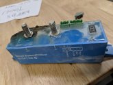
If you don't know what DIN rail components look like,
It's a way to keep things neat and
organized, and about everything you can think of is made in DIN mounts,
This is a Solar Combiner box with breakers, disconnects and other stuff.
DIN rails can be screwed down about anywhere, but this is what they were intended for.


1578674936322.png
 
  • Like
Reactions: Dzl
The problem is a combination of the high inrush current of the inverter charging its capacitors and the delicate logic of the BP. A common 2kVA inverter can pull between 500 and 600A for a matter of milliseconds when it charges its capacitors; although this (depending on the BP model) may not exceed the BP's current rating, the speed with which it happens makes the logic of the BP think that it's a short circuit, which will trigger an E1 short circuit error and the BP won't connect the load.

Ok seems to me that anything with very high inrush current would do it.
I guess the other applications are extreme outliers.
 
@JeepHammer you should have your keyboard checked out, the caps lock keeps getting stuck. Otherwise, (y) have at it bud. I'm not here to hawk my stuff; quite the contrary, I'm literally here saying don't buy Victron equipment for this application, and repeatedly advising people that there are other and cheaper ways to do what they want. I'm the tech guy, not a salesman.

Haven't argued with you about any of your other ways of doing what you want to do... I came into this thread because you said a Victron component could be connected in a way that it cannot. So long as you stop saying that, we're good.
 
Status
Not open for further replies.
Back
Top