diy solar

diy solar

CAN and RS485 BMS Interface with multiple emulated Inverter protocols for JkBms Jbd BMS Daly 123Smart

Hey,

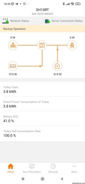
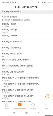
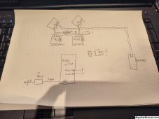
My batterypack (48s) is already connected with the inverter. i had tested CAN and RS458 already and it didnt work. the easy way would be to connect this block. But i would like to have the full 66s. I would like to buy and use 3 JK acitve balancers and wire them. how would the CAN connection between the devices look like?

U can use an "middle man" interface to convert daly can -> interface -> sangrow can
 
Ok, i will order componets for daly/sungrow as you wrote. i will also buy the other componets for the 66s stuff(3 JK balancer, Interface for sungrow).
after we managed to get the 48s work, can you help me also with the 66s?
I will write you after my vacation at the start of novmeber.
 
Ok, i will order componets for daly/sungrow as you wrote. i will also buy the other componets for the 66s stuff(3 JK balancer, Interface for sungrow).
after we managed to get the 48s work, can you help me also with the 66s?
I will write you after my vacation at the start of novmeber.

Ok, write when u are ready, for middle man u need interface with 2 can port.

Can use some arduino due woth 2 port adaptor.

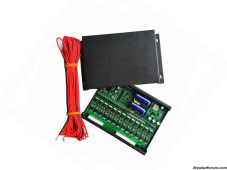
For 66 pack u need aome jk balancers

The protocol work with 10rt no problem.

IMG-20231021-WA0002.jpgIMG-20231021-WA0001.jpg
 
OK for the 48 S
Esp32 DevKit 1
2X CAN : SN65HVD230
? RS485: Max485
DC-DC: XL7015
2 RJ45 Breakout
Optional: Indicator LEDs

For The 66 S
3 X JKB2A24s
? JK BD62A2412P

Esp32 DevKit 1
3 X CAN : SN65HVD230
? RS485: Max485
DC-DC: XL7015
2 RJ45 Breakout
Optional: Indicator LED

is This OK?
 

Attachments

  • 1698001596451.png
    1698001596451.png
    281.3 KB · Views: 7
OK for the 48 S
Esp32 DevKit 1
2X CAN : SN65HVD230
? RS485: Max485
DC-DC: XL7015
2 RJ45 Breakout
Optional: Indicator LEDs

For The 66 S
3 X JKB2A24s
? JK BD62A2412P

Esp32 DevKit 1
3 X CAN : SN65HVD230
? RS485: Max485
DC-DC: XL7015
2 RJ45 Breakout
Optional: Indicator LED

is This OK?

For 48S u can try to read RS485 or Serial from Daly So u will need :
Esp32 DevKit 1

1 X CAN : SN65HVD230 - for inverter
1 RS485: Max485 - to read data from daly / or use direcy UART
2 RJ45 Breakout
1 DC-DC: XL7015 - take power form daly 12V pin

For 66s
1 x JKBMS + 2 jk balancer if u want to read the current also
2 X CAN : SN65HVD230 - for inverter
1 x CAN MCP2515 - will need to swat the tranciver with the SN65HVD230
1 RS485: Max485 - to read data or use direcy UART
2 RJ45 Breakout
1 DC-DC: XL7015 - take power form daly 12V pin
 
I got ESP 32 starter kitV4, do you have a switch plan for this?If I use two SN65HVD230, are TX and RX supplied separately? Do I need a JST 4pin socket?What is connected to D18 and D 19?Greetings Peter1698529033405.jpg1698529033408.jpg1698529033408.jpg
 
U can serch for other can tranciver module. Or buy one from ebay. Be shure is compatible with 3.3v
I receive the Can module and i connect it to the D4 and D5, 3.3v and GND as well.
Can L and Can H s connected to the pin 4 and 5 on the growatt spf5000 set on Li (Program 5) and protocole 52 (Program 36)
but it seem always have no communication between the invetor and the BMS.
ESP32 is connected BT on the JKBMS.
Can you help to see if I make somethink wrong?
1698849800590.png
 
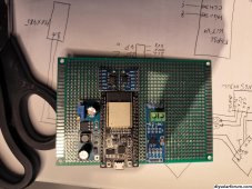
This is the simple way to build it DIY , only with CAN port because most of invertors support CAN protocols!

BOM:
Proto PCB 5x7cm
Esp32 DevKit 1
CAN : SN65HVD230
DC-DC: XL7015
RJ45 Breakout with leds
2 x 220R or 330R resistors
1 4 Pin JST 1mm pitch cable


In my Google Drive find Stl file for 3d Printing

The SN65HVD230 is under the ESP board!

View attachment 160535

Few Soldering
View attachment 160536

3d Printed Case
View attachment 160537

Final assembly
View attachment 160538


JK - Sungrow HV

View attachment 160539View attachment 160540
How did you get the Sungrow to work with BYD HV protocol? I can't see it in the list of CAN protocols, only LV protocols.
 
How did you get the Sungrow to work with BYD HV protocol? I can't see it in the list of CAN protocols, only LV protocols.
For hv i use deferent setup, i described before u need to use a combination of jk balancer with can port and interface with 2 can ports one for battery one for inverter
 
I got ESP 32 starter kitV4, do you have a switch plan for this?If I use two SN65HVD230, are TX and RX supplied separately? Do I need a JST 4pin socket?What is connected to D18 and D 19?Greetings PeterView attachment 174799View attachment 174800View attachment 174800
XL7015 is set to 5v on output.
ESP32 support 1 can port d4 d5
second can port u need to use mcp2515 board and swap the tja chip with sn65v because tja is on 5v

For hv setup is impotent to divide ur pack to have same number of cell for each balancer or bms because they feed them self with power from battery and if u have for example 23S on first jk and 15s and jk take 10w to work first will take 10w from 23s and second from 15s and second will discharge more the 15s cells.
 
If some of u build the interface and have problems and need support write me in pm and i will give u my Whatup contact to speed up debug process for u in next 2 weeks.

After 15.11.2023 i will migrate the project on dedicated hardware kit.

For first 2 version last freeware will be 5.x

I wish to split the channel in 2 deferent topics LV / HV because is hard for me to track all and maybe i dont answerer to all.

Also with the new hardware i will upload video for installation / debug / support.
 
For hv i use deferent setup, i described before u need to use a combination of jk balancer with can port and interface with 2 can ports one for battery one for inverter
XL7015 is set to 5v on output.
ESP32 support 1 can port d4 d5
second can port u need to use mcp2515 board and swap the tja chip with sn65v because tja is on 5v

For hv setup is impotent to divide ur pack to have same number of cell for each balancer or bms because they feed them self with power from battery and if u have for example 23S on first jk and 15s and jk take 10w to work first will take 10w from 23s and second from 15s and second will discharge more the 15s cells.
Thank you. :) Yes, in going to use one JK BMS and four balancers for my 96s setup and dual can ports as you described. If I understood right about dividing the packs on same amount for balancer outputs I need to use 19 balancer outputs per balancers and 20 balancer outputs on the JK BMS to get all the outputs splitter over all the cells, right?
 
something is not ok on ur settings u have 0 on can charge discharge current.

Also try to see if ur can transiver is not broken. some cheap one can be fault from factory, some user have this problem and change the tranciver and was ok.
Ok i will try to get new one.
 

diy solar

diy solar
Back
Top