diy solar

diy solar

CAN and RS485 BMS Interface with multiple emulated Inverter protocols for JkBms Jbd BMS Daly 123Smart

How did you get the Sungrow to work with BYD HV protocol? I can't see it in the list of CAN protocols, only LV protocols.
For hv i use deferent setup, i described before u need to use a combination of jk balancer with can port and interface with 2 can ports one for battery one for inverter
 
I got ESP 32 starter kitV4, do you have a switch plan for this?If I use two SN65HVD230, are TX and RX supplied separately? Do I need a JST 4pin socket?What is connected to D18 and D 19?Greetings PeterView attachment 174799View attachment 174800View attachment 174800
XL7015 is set to 5v on output.
ESP32 support 1 can port d4 d5
second can port u need to use mcp2515 board and swap the tja chip with sn65v because tja is on 5v

For hv setup is impotent to divide ur pack to have same number of cell for each balancer or bms because they feed them self with power from battery and if u have for example 23S on first jk and 15s and jk take 10w to work first will take 10w from 23s and second from 15s and second will discharge more the 15s cells.
 
If some of u build the interface and have problems and need support write me in pm and i will give u my Whatup contact to speed up debug process for u in next 2 weeks.

After 15.11.2023 i will migrate the project on dedicated hardware kit.

For first 2 version last freeware will be 5.x

I wish to split the channel in 2 deferent topics LV / HV because is hard for me to track all and maybe i dont answerer to all.

Also with the new hardware i will upload video for installation / debug / support.
 
For hv i use deferent setup, i described before u need to use a combination of jk balancer with can port and interface with 2 can ports one for battery one for inverter
XL7015 is set to 5v on output.
ESP32 support 1 can port d4 d5
second can port u need to use mcp2515 board and swap the tja chip with sn65v because tja is on 5v

For hv setup is impotent to divide ur pack to have same number of cell for each balancer or bms because they feed them self with power from battery and if u have for example 23S on first jk and 15s and jk take 10w to work first will take 10w from 23s and second from 15s and second will discharge more the 15s cells.
Thank you. :) Yes, in going to use one JK BMS and four balancers for my 96s setup and dual can ports as you described. If I understood right about dividing the packs on same amount for balancer outputs I need to use 19 balancer outputs per balancers and 20 balancer outputs on the JK BMS to get all the outputs splitter over all the cells, right?
 
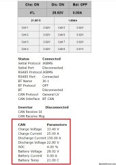
something is not ok on ur settings u have 0 on can charge discharge current.

Also try to see if ur can transiver is not broken. some cheap one can be fault from factory, some user have this problem and change the tranciver and was ok.
Ok i will try to get new one.
 
Is it correct that 5 wires are clamped together between the balancers?

Is it correct that 5 wires are clamped together between the balancers?

NO! There are not clamped tother 5 wires!!!

Last cell form first module is connected also to first cell of next module!
in photo is like that:

cell 24 + is connected with jk1 24 wire + jk1 VCC + Jk2 1Wire
cell 24 - is connected with jk2 -
 
I upload last version for DIY boards 5.1 bugs on rs485 connection was fixed


Serial 1 - Serial BMS connection
Serial 2 - RS485 BMS connection

if u have more battery module and want to use only 1 interface u can override the max charge current and max discharge current for all pack.

v52.jpg

Data send it to inverter can be see and verify in info page

v51.jpg

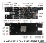
From here project will be migrated to LILYGO T-CAN

If u want to support the project can buy the kits from my Ebay & PayPal

t-can.jpg
 
I upload last version for DIY boards 5.1 bugs on rs485 connection was fixed


Serial 1 - Serial BMS connection
Serial 2 - RS485 BMS connection

if u have more battery module and want to use only 1 interface u can override the max charge current and max discharge current for all pack.

View attachment 178491

Data send it to inverter can be see and verify in info page

View attachment 178492

From here project will be migrated to LILYGO T-CAN

If u want to support the project can buy the kits from my Ebay & PayPal

View attachment 178494
Does 5.1 work with HV setup?
 
Hi @mrconstantin
I will try use you solution with goodwe gw10k-et and 2 jkbms.
That new firmware v5.1.0 wants wifi pass to connect.
on 4.3 version i have chip id: db32a7b0
 
wifi pass is chipID

et is hv invertor u need hv battery
Hi, i have battery which are used in VW - LG-CHEM (PN 0Z1915 599 H) 6.85kWh / 234Ah / 29.6V - 8s3p - 6 pcs and 2 jk-bms jk-b2a24s15p-c
I don't know if it is enough to use wit gw10-et. it need minimum 180v to work. if it will be not enough i can put into string another set - 3 battery and jkbms.

 
Hi, i have battery which are used in VW - LG-CHEM (PN 0Z1915 599 H) 6.85kWh / 234Ah / 29.6V - 8s3p - 6 pcs and 2 jk-bms jk-b2a24s15p-c
I don't know if it is enough to use wit gw10-et. it need minimum 180v to work. if it will be not enough i can put into string another set - 3 battery and jkbms.


u need at least 7 x 8s pack = 56S x3.3V =184V
 
Back
Top