diy solar

diy solar

Can I revive these seemingly dead panels?

HalfBaked

Ever the student
Joined
Jun 6, 2023
Messages
216
Location
Upper Mississippi Delta
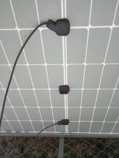
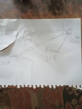
So while I had my back turned, upgrading my system from 12 to 48v, my midday array quit on me. I'm sure it's my fault, as I had these 3 panels in parallel without fusing between panels. (Now I know better). But these 3 have been working in this configuration for a couple years without issue.

Anyway, I feel that I have eliminated everything but the panels themselves. (Breakers, cables, connectors). All 3 show good voltage with the DMM, but no amps with the clamp once connected individually.

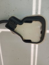
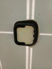
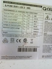
I looked to see if there were serviceable fuses in the back, but didn't see any (pics attached). I have never had to troubleshoot/fix a panel and am a bit lost. I searched first but couldn't find anything relevant.

Can anything be done?

Hanwha Q Cell 385w Mono Duo Cell
 

Attachments

  • IMG_20230812_113041352.jpg
    IMG_20230812_113041352.jpg
    63 KB · Views: 3
  • IMG_20230812_112940367.jpg
    IMG_20230812_112940367.jpg
    42.6 KB · Views: 3
  • IMG_20230812_112841698.jpg
    IMG_20230812_112841698.jpg
    98.1 KB · Views: 3
Short each individual panel by connecting it's positive and negative MC4s together. What current do you read then? Be sure your clamp ammeter does read DC current and that it is zeroed.
 
That should compare pretty well with the panel's listed short circuit current, but it will vary with solar insolation on the panel. You already said the open circuit voltages were good ( the voltage should compare even closer to the spec open circuit voltage).

In short, doesn't seem to be anything wrong with at least the panel(s) you tested. Can you sketch a wiring diagram of your system?
 
I have tried using known good wires and breakers to no avail. Other 2 arrays have no problems.
 

Attachments

  • IMG_20230812_124404451.jpg
    IMG_20230812_124404451.jpg
    87 KB · Views: 13
  • IMG_20230812_123458793~2.jpg
    IMG_20230812_123458793~2.jpg
    149.1 KB · Views: 13
You have 3 40-volt panels in parallel trying to charge a 48 volts battery. That math doesn't work out unless you have a charge controller with a boost converter built in.
 
You have 3 40-volt panels in parallel trying to charge a 48 volts battery. That math doesn't work out unless you have a charge controller with a boost converter built in.
Thanks for that. But I just upgraded from 12 to 48v. During that, the array quit. So never had a chance to reconfigure.
 
Maybe a diagram of your system before and after the upgrade would help me understand?

Because you upgrading from 12-volts (less than your 40 volts from solar, would work fine) to 48-volts (more than the 40 ish volts the array can output) still sounds like the problem.
 
Maybe a diagram of your system before and after the upgrade would help me understand?

Because you upgrading from 12-volts (less than your 40 volts from solar, would work fine) to 48-volts (more than the 40 ish volts the array can output) still sounds like the problem.
The diagram above is the same now as before the upgrade. I see what you're saying, that the upgrade to 48v is the "problem", but shouldn't I still be able to measure some amps on the wire at the combo box?
 
Agree with 400bird. Any panel configuration which parallels two or more panels individually is a problem unless the panel wiring is really weird. The voltage at the SCC input will be too low. What is the maximum PV input voltage allowed by the SCC?
 
Agree with 400bird. Any panel configuration which parallels two or more panels individually is a problem unless the panel wiring is really weird. The voltage at the SCC input will be too low. What is the maximum PV input voltage allowed by the SCC?
Yes, that does make sense. Should I be able to measure any amps even though the voltage is too low for the system?
The SCC is a 150v/60a
 
The diagram above is the same now as before the upgrade. I see what you're saying, that the upgrade to 48v is the "problem", but shouldn't I still be able to measure some amps on the wire at the combo box?
I missed the diagram from earlier.
The mid day array "died" because it is the only 1s array.

Current flows from higher potential (voltage) to lower. So, no current will flow from the 40 volts panels up to your 48 volts battery.

What is your charge controller? Can you switch those 3 panels to 3s?
 
No, you'll only measure current if the SCC draws it. If the battery voltage is 48, the PV voltage will have to be greater than that by probably at least 10V for it to draw any current from the PV, unless your's has a boost converter in it, and that is unlikely.
 
The SCC is a 150v/60a
That's awful close to the limit for 3s at 48 volts open circuit. Probably fine for a test in the summer. If your winter or summer morning is even remotely cool, you'll exceed 150 volts and risk killing the charge controller.
 
I missed the diagram from earlier.
The mid day array "died" because it is the only 1s array.

Current flows from higher potential (voltage) to lower. So, no current will flow from the 40 volts panels up to your 48 volts battery.

What is your charge controller? Can you switch those 3 panels to 3s?
Thanks for all this. All becoming clear now. Going to wire them 3s1p now and remove one before the next freeze.
 
Do you have multiple charge controllers? Or multiple MPPTs in that one charge controller?

You've got a combiner box, so I'm guessing not. How did the mid day array ever work? It's in parallel with the 3s arrays. Not a great set up.
 
Back
Top