diy solar

diy solar

Can Someone please explain the math to actual amps being pulled from the battery to an inverter?

Dadoftheturkeykids

New Member
Joined
Jan 11, 2024
Messages
91
Location
U.s.
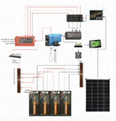
I am trying to size a class-t fuse for my offgrid setup.

My inverter is 3000w continuous+ surge
I will only be pulling 2400 continuous at any given time but I want my fuse to cover up to 3000watts.

I understand that power out is not equivalent to power in, because of conversion losses.

Can someone please explain the formula to find what amperage is being drawn from my batteries @ 3000watts?

I'm not sure if I calculate the actual common voltage of my battery bank @13v-13.2v
Or just simplify it to 12v.
Also if I'm calculating for efficiency of 85%, does that mean that I multiply the output wattage by 1.15?

Sorry if this sounds too basic for me not to understand but I'm in need of some clarification.

Thanks in advance :)12v picture (1).png
 
Last edited:
If you have an 85w load on the ac side and provide 100w on the dc side - that's a 15% efficiency lost. 85w * 1.18 = 100.3w.
So yes, 1.15 (or 1.18) is in the ball park for 85% efficiency.

However, inverter efficiency can varies depending on the % load on the the inverter compared to it's maximum output - so it's not quite as clean as just using 1.15 for all circumstances.

One can measure these numbers for the specific load and inverter on both sides of the inverter for more precise info.

If you don't measure, then add a bit of fluff. For example, 3000w on 12v is A LOT of amps. 3000w * 1.15 = 3450w / 12v = 287a wire/breaker. You're not going to find 'exactly' 287a breakers - so go with 300a or 400a type of thing.
 
Last edited:
just simplify it to 12v.
That gives ‘buffer’
Also if I'm calculating for efficiency of 85%, does that mean that I multiply the output wattage by 1.15?
Divide 3000W by .85 for that or

3000W divided by 120VAC yields 25A which is 250A at 12VDC
250/.85=295 so 300A cables and a 300A fuse fits.

And you said
but I want my fuse to cover up to 3000watts
And that could be fine
 
trying to size a class-t fuse for my offgrid setup.

My inverter is 3000w
3000W / .85 efficiency / 10V inverter cutoff = 353A

Fuse should be 1.25x to 1.5x higher to prevent nuisance blows. 500A fuse a good choice.

But since the fuse protects the wire, your wiring would need to withstand 500A and that is a difficult requirement to achieve. Looking at it the other way around, what wiring will you have? Select a fuse that protects your wires.
 
FWIW on my 2000W 12V inverter I used 2/0 cables to a busbar, and a 160A ANL fuse in-line of the inverter.

The three batteries are 4800Wh or ~5kWh depending on how I lie to myself, each having a 100Ah bms. There is a 100A Class T directly on the battery pos(+) like there should be. ANL’s are ~$2/each and Class T’s are ~$40.

That’s a consideration.
 
The three batteries are 4800Wh or ~5kWh depending on how I lie to mymyself
I lol'd at this.. I call my 4-545 watt panels 2.2kw.. which is close, and my 4-200ah batteries 10kwh, which is a little less close. But again, I'm not sure if I'm supposed to calculate a simplified 12v x 200a to get the watt hour rating.

All 4 of my batteries are connected in parallel with 4/0 copper welding wire (200a breakers on each positive, i will be upgrading to mrbf) and the same 4/0 goes to my inverter (which is where I was going to place my t-fuse)
 
3000W / .85 efficiency / 10V inverter cutoff = 353A

Fuse should be 1.25x to 1.5x higher to prevent nuisance blows. 500A fuse a good choice.

Looking at it the other way around, what wiring will you have? Select a fuse that protects your wires.
It is to my understanding that 4/0 wire is capable of 480amps, so I shouldn't use a 500amp fuse, correct?
 
My 2 cents - your looking at it backwards - fuses are to be 125% of whatever the max possible supplied current - Fuses only protect wires from melting or tools if you manage to drop them across the battery posts.

Put a MRBF fuse with holder on top of your positive battery post.
Size the fuse to 120% or so of the max current the battery BMS can put out.
Most batteries at 12v can only put out either 100a or 200a depending on the model. so either a 125a or 250a fuse.

If you string more than one battery together each battery gets its own fuse. If you string more than two batteries together you need to use bus bars. In that case the batteries keep the MRBF fuses, that protects against a dropped tool.

Wires between the batteries and bus bars - 1awg welding wire - 105c - windy nation is a good brand

I just saw your most recent post -

Bus bars should carry max current + 20% -
Add up the current of your 4 batteries and make sure your busbar can handle that current - assuming only 100a per battery that is 400amps - So it warrants 600amp bus bars. If the batteries can put out 200amps you need something that can handle 800amps which means 1000amp bus bars.

You can make your own busbars cheaper that buying them in that range - you need pure copper bus bars 1.5" wide and 1/4" thick.

After the bus bar attach a class T fuse holder and fuse with your 4/0 wire and size that fuse at 300amps. Technically 2/0 would work as long as it is the welding wire with a 105c rating.

And I know you are thinking why have bus bars rated at 1000amps, I will never pull it!!! ... what if your positive and negative leads out of the bus bars touched - would you rather blow fuses or have wires melting or bus bars melting?

The larger bus bars also allow for the current from the charging sources be it SCC or an inverter/charger or a wall charger plugged into the house?

Off the negative pole wire to another bus bar - then cut off switch then shunt - then the inverter.

Attached is a drawing I did a while back for someone with a virtually identical setup.

BTW - I would never use an ANL fuse in this setup - it doesn't have any arc extinguishing to speak of and MRBF typically have 20ka and the Class T typically has 50ka


1711220927428.png
 

Attachments

  • 12v picture.png
    12v picture.png
    496.8 KB · Views: 9
Last edited:
It is to my understanding that 4/0 wire is capable of 480amps, so I shouldn't use a 500amp fuse, correct?
MrSandals may provide that literal answer.

In practical terms? I’d personally use a 250- or 300A fuse of some sort for the inverter, but always just use a Class T directly on lithium batteries.
 
All 4 of my batteries are connected in parallel with 4/0 copper welding wire (200a breakers on each positive, i will be upgrading to mrbf) and the same 4/0 goes to my inverter (which is where I was going to place my t-fuse)
The placement and order of your fusing seems odd to me.

Consider this discussion, post #13 in particular, that explains why one would use a class T fuse in the first place (AIC rating) and where it would be most useful (on each battery post):

 
All 4 of my batteries are connected in parallel with 4/0 copper welding wire (200a breakers on each positive, i will be upgrading to mrbf) and the same 4/0 goes to my inverter (which is where I was going to place my t-fuse)

Not sure of your setup but keep in mind that the 4/0 cable is now allowed to get 800 amps unless you have the fuses at a busbar and then yet another fuse on the busbar to the inverter.

For a 3000 watt 12v inverter with 6000 surge, use like a 450 amp fuse.

Load test with a big surge and then draw max continuous. If it doesn't blow then you're good.

If it blows then go up a size.
 
Attached is a drawing I did a while back for someone with a virtually identical setup.
Its virtually identical because it literally my system haha. Thanks for the continued help.


The placement and order of your fusing seems odd to me.
My breakers are on all my positive leads going to a mutual busbar.

I have not upgraded to mrbf fuses yet but now I'm overthinking this whole thing, I need 5 class-t fuses?
 
Back
Top