I wound up just getting a power supply, this kit, an RD6012w (they are up to RD6018/RD6018w now):
Smarter Shopping, Better Living! Aliexpress.com

www.aliexpress.com
I use it also, working with 48v DC motors lately too, so it serves other purposes, I'm building an off grid homestead, and toying with DC motors to drive things like greenhouse fans, pumps, and solenoids, testing temperature switches, PWM controllers, and other stuff running on DC 48v, so a power supply can be a handy thing to have around anyways, depending on your situation.
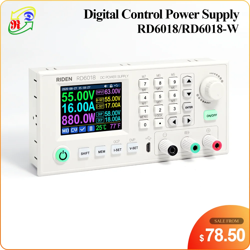
Here is the RD6018/RD6018w:
Smarter Shopping, Better Living! Aliexpress.com
www.aliexpress.com
It requires the main buck converter front panel (the heart of it), a case, and the backend steady-state regulated power supply, lots of You Tube videos showing how to assemble the kit. I bought all 3 components from the Factory RD Store on AliExpress, using the Ships from United States option and they came pretty fast.
View attachment 27574
As far as balancing, I would just stick with Will's (no frills, no gimmicks) top balancing video:
He basically just connects all cells in parallel, and runs them up to 3.65v, with the power supply set to Constant Voltage (I just set to Constant Voltage to 3.64v, and OverVolt Protection to 3.65v) and call it good once the current goes down to 0.