diy solar

diy solar

Cell Voltage Difference and Bus Bar Question

wpduhe

New Member
Joined
Jun 30, 2022
Messages
36
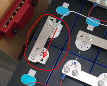
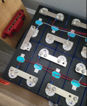
I have a 48V 16S pack oriented with cells 1-8 (top/right) and 9-16 (bottom/left). Cells 8 and 9 are connected by a perpendicular bus bar that doesn't make full contact with the cell terminals. I would like to know if I should get a custom bus bar to make full contact with the cell terminals. I'm not sure if this inconsistency can lead to an increase in imbalance amongst the cells. Quick example: with just a 25A load the cell voltage difference can be greater than 0.25V across cells 8 and 9. This was tripping my cell voltage difference protection and making me scratch my head at first as to why my battery was shutting down (Daly BMS did not log or show this was the cause of disabling discharge).

2 questions:

1. Would this perpendicular bus bar be the cause of this voltage imbalance? Cells were top balanced to 3.65V. Stopped balancing when the cells reached 40mA of current and the cells read 3.646V.
2. Would making a custom bus bar that makes full contact with the cell terminals result in more even discharge of these cells?

Thanks All!
1661523639717.png
 
1. Possibly, but .25 seems excessive. The slot seems to remove a significant amount of the contact area.

  • Do you see a similar voltage increase with 25A charging?
  • .25 * 25A = 6.25W - this should be enough to feel some heat. Do you feel any warmth compared to the other bus bars after ~15minutes @ 25A?
  • Are all nuts torqued properly to 4-6Nm?
  • Are the sensing leads of high quality, good crimps, etc.?
  • Do you see different behavior if you move the sensing lead to the (-) of cell 9.
  • Do you have any more bus bars? If so, could you fit two side by side?
  • Do you have any heavy gage wire, 2awg or better, that you could use to connect the other half of the terminal?
  • Why do the others have only 3 fasteners when a 4th is available?

2. The discharge is even from an Ah perspective because all cells pass the same current. The voltage drop causes a loss in watts at that cell producing additional heat. The reverse happens when charging - voltage increase results in watts loss at the terminal.
1. This pack is fully off-grid so it never sees 25A charge rate. The most it's ever seen is 8A with 443W PV input. I don't have a 48V charger so couldn't test it if I wanted to.
2. Without using a thermometer, it does seem that some bus bars are warmer than others. Nothing is hot. I will check with a thermometer if the one I have will work.
3. This is a temporary state for testing so I haven't torqued anything and I haven't installed all of the studs and nuts. If that is the recommendation then I will seek a torque wrench.
4. The sensing leads were crimped and soldered. Probably not the best quality, but I suspect that it should be sufficient for voltage readings.
5. I don't believe I can move the BMS cell 9 lead to the negative terminal as the wiring diagram dictates that it should be on the positive terminal. This would cause the BMS to power off or even destroy it if I'm not mistaken.
6. I do have another bus bar, but it will not fit beside it. I'm considering getting a piece of copper and making a custom bus bar to fit this orientation if the bus bar connecting cells 8 and 9 is indeed a problem.
7. No heavy gauge wire... yet.
8. See answer 3.

I will also put my multimeter on the cells to check their voltages that way. But if the BMS is seeing something I cannot see with the multimeter then it will shut the pack down regardless. I suppose this could mean that the balance cable leads would be sub-standard and will need work.

Thank you for your response. I will provide updates.
 
Additional question: What would be an acceptable cell voltage difference during high current discharges?
 
1. This pack is fully off-grid so it never sees 25A charge rate. The most it's ever seen is 8A with 443W PV input. I don't have a 48V charger so couldn't test it if I wanted to.

Gotcha

2. Without using a thermometer, it does seem that some bus bars are warmer than others. Nothing is hot. I will check with a thermometer if the one I have will work.

If it's that subtle and inconsistent, you likely have multiple connection issues.

3. This is a temporary state for testing so I haven't torqued anything and I haven't installed all of the studs and nuts. If that is the recommendation then I will seek a torque wrench.

You're not technically testing anything but an untorqued, incomplete assembly of cells that resembles a battery. You should expect issues to arise from the lack of completion.

4. The sensing leads were crimped and soldered. Probably not the best quality, but I suspect that it should be sufficient for voltage readings.

Gotcha

5. I don't believe I can move the BMS cell 9 lead to the negative terminal as the wiring diagram dictates that it should be on the positive terminal. This would cause the BMS to power off or even destroy it if I'm not mistaken.

1661530182656.png

Do you see how this is effectively all the same terminal? #9 negative is #8 positive?

Disconnect the sensing harness from the BMS, move the terminal, plug the harness back in.

6. I do have another bus bar, but it will not fit beside it. I'm considering getting a piece of copper and making a custom bus bar to fit this orientation if the bus bar connecting cells 8 and 9 is indeed a problem.

Can you simply drill the holes a little larger allowing some side-to-side movement?

7. No heavy gauge wire... yet.
8. See answer 3.

Gotcha

I will also put my multimeter on the cells to check their voltages that way. But if the BMS is seeing something I cannot see with the multimeter then it will shut the pack down regardless. I suppose this could mean that the balance cable leads would be sub-standard and will need work.


Any BMS reading should be confirmed with a multimeter. That should have been my first question. Expect inaccuracies in all sensing devices unless you know they're calibrated.

Additional question: What would be an acceptable cell voltage difference during high current discharges?

In a system built with best practices - maybe 0.02V?

EDIT: My 4-6Nm torque recommendation is based on the M6 thread spec for a different kind of Eve terminal. Confirm your torque specs with the cell datasheet.
 
In a system built with best practices - maybe 0.02V?

EDIT: My 4-6Nm torque recommendation is based on the M6 thread spec for a different kind of Eve terminal. Confirm your torque specs with the cell datasheet.

Additional Data:
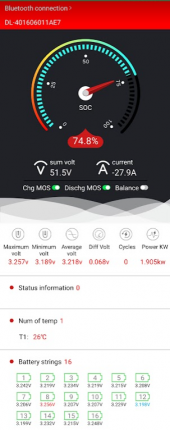
When checking with the multimeter, all cell voltages while under load were within 0.002V of one another, lowest reading 3.263V, highest 3.265V. So that falls within the range of your best practice number above. BMS saw completely different voltages. Screenshot below.

Temperature readings ranged from 90.1 to 91.5 (F). Cells 9-16 are closer to the inverter and the bus bars read on the higher end of that range. Cells 1-8 further from the inverter and the bus bars read on the lower end.

1661532954405.png
 
Idle data:

The BMS reads cell voltages slightly higher than the multimeter does. The multimeter reads 3.289V on all cells and the BMS reports 3.291V.
 
As I said elsewhere , expect +- 25mV error or 50mV total error in these readings , current accuracy is usually much worse
 

Attachments

  • 6C649373-A068-4D15-9AFE-1E1B9C81BB98.jpeg
    6C649373-A068-4D15-9AFE-1E1B9C81BB98.jpeg
    270 KB · Views: 6
Additional Data:
When checking with the multimeter, all cell voltages while under load were within 0.002V of one another, lowest reading 3.263V, highest 3.265V. So that falls within the range of your best practice number above. BMS saw completely different voltages. Screenshot below.


Idle data:

The BMS reads cell voltages slightly higher than the multimeter does. The multimeter reads 3.289V on all cells and the BMS reports 3.291V.

This SCREAMS connection issues.


EDIT: .002-ish differences between BMS and meter is noise. Unless you're using calibrated equipment, assume readings within ±.01V are the same.
 
This SCREAMS connection issues
I'm at the point where I just don't trust this Daly BMS. The meter reads good, but every time I try to pull 50A the BMS shuts the pack down instantly. Guessing due to cell voltage difference that it thinks is present. Can't show this problem outside of the BMS. But it's causing me problems. Will be an even bigger problem if it does this while I'm operating the electric motor it's planned to power. I'm going to get everything torqued and see if that makes a difference.
 
A Bms is doing well to have +- 25 mV resolution on voltage
Under load, I'm well beyond 25mV delta. The max I've seen is 275mV difference. I even had cell difference protection set to 500mV, applied 50A load, and tripped the BMS.
 
I'm at the point where I just don't trust this Daly BMS. The meter reads good, but every time I try to pull 50A the BMS shuts the pack down instantly. Guessing due to cell voltage difference that it thinks is present. Can't show this problem outside of the BMS. But it's causing me problems. Will be an even bigger problem if it does this while I'm operating the electric motor it's planned to power. I'm going to get everything torqued and see if that makes a difference.
I develop my own BMS. firstly getting a BMS to very accurately measure voltage requires expensive circuitry and design care. 10 bit ADC convertors give about 4mV ( on 4V dynamic range ) resolution plus +-2 counts ,hence +-10mV , total 20mV is a very good result ( this assumes you can keep the circuit noise floor below this , which can be a challenge on a boat or RV )

I have a number of logging multimeters and its useful to track cells in a battery pack over time . Usually high current shutdown is because in a series string one of the cells experienced voltage collapse ( assuming the BMS is rated for this current ) and the BMS shut the battery down . The other thing is ensure you have significant headroom in the BMS current limit , first you must be able to supply the initial current inrush especially for inductive loads ( motors, invertors , etc ) , secondly the current measuring in a BMS is often very sloppy , with -+ 10% of FSR or even more being common , so in a say 100A limit, you could errors of 20 amps in the limit trigger .
 
I'm at the point where I just don't trust this Daly BMS. The meter reads good, but every time I try to pull 50A the BMS shuts the pack down instantly. Guessing due to cell voltage difference that it thinks is present. Can't show this problem outside of the BMS. But it's causing me problems. Will be an even bigger problem if it does this while I'm operating the electric motor it's planned to power. I'm going to get everything torqued and see if that makes a difference.

This may be the case, but given that you haven't engaged in best practices, you're still testing "an untorqued, incomplete assembly of cells that resembles a battery."

Take a step back.

Unplug BMS harness.
Remove all sensing wires.
Remove all bus bars.
Buff all the aluminum terminals as Al oxidizes and can inhibit current.
Replace all bus bars
Replace all sensing leads.
"snug" up all the connections. Be firm, but don't overdo it. Try to be very consistent. Maybe actually get that torque wrench.
Plug in BMS harness.

Re-test.
 
This may be the case, but given that you haven't engaged in best practices, you're still testing "an untorqued, incomplete assembly of cells that resembles a battery."
I will do this. I will also pull out my benchtop power supply and hook it up to the balance cable leads to test for voltage consistency across those leads with my multimeter (to test my amateur soldering job). Thanks for your time today!
 
"snug" up all the connections. Be firm, but don't overdo it. Try to be very consistent.
Did this and it worked!! I suppose I was too paranoid about stripping out those aluminum threads. I tightened everything as consistently as possible and pulled 53A from those batteries for more than 30 minutes. I will get that torque wrench!! I'm going to top balance these again since the build was improper and probably caused them to discharge differently. The next time I build it, everything will be torqued.

Thanks to everyone who offered advice!
 
Back
Top