diy solar

diy solar

Charging parallel connected battery modules with sperate BMS

kostkaaa

New Member
Joined
Jul 9, 2020
Messages
1
Hello, my question: Is it possible to charge parallel connected battery modules with seperate BMS save or is it only save to parallel them for higher current load.
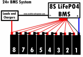
Have seen this picture on the website and it only shows "load" and not loads and chargers like on the other pictures too. website: www.mobile-solarpower.com
Thank you!
BMS2.PNGBMS3.PNG
 
Just like with discharging from all "packs" within the bank, the charge capacity is shared between the packs within the bank.
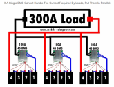
If you have Three 12V/100AH with 100A BMS packs, properly wired in parallel they should split the load demand & charge capacity. Should one pack reach "full" before the others the BMS should disconnect it to protect it from overcharging, the balance of charge power would then be split between the other two.

Typically with FET Based BMS', if the BMS is rated for 100A output, the most they can usually handle is generally 50A for Charging, or simpler yet 1/2 of what can be discharged. Using the same example, you'd have 300A Output capacity and 150A Charge capacity "collectively" from the bank.

To further on this, assuming 3 packs of 12V/100AH capacity, each with a FET based BMS capable of 100A discharge & 50A charge.
The load split can technically handle up to 300A max if all packs are active and it's all properly wired. If one pack reaches "Empty 'LVD' cut off" before the other 2, the load will be split between the two remaining, could only handle up to 200A Max Output.
Charging from SCC, Inverter/Charger or dedicated charger could only be 50A (limited by BMS). Now if you have 3 Packs being charged that is 50A ÷ 3 packs, then each pack is only getting about 16A so that will be a slow charge. If one pack hits full, then the 50A will be split between the remaining two and so on.

The Catch lurking in the bank !
Ultimately you are limited to the Maximum Amps that can be pushed for charge to the bank as a whole. Yes, if all three packs were at 20% SOC, you could push 150A and the three would take it BUT when Pack-A hit's full the available AMPS to Charge will be over what the other two BMS' can take and they would shut down to protect the packs. NOTE that Most "Common / general" LiFePo4 cells can handle 1C Rate for charge & discharge. which for a 100AH cell, that means up to 100A Charge / Discharge rate, the bigger the cells (ie: 280AH) the higher the amp capacity but also longer to charge or discharge as well.

Building to the "Common Denominator".
The two main factors here are Discharge Capacity and Charge Capacity which is relative to the battery packs within the bank as a whole.
The BMS chosen for each pack, should be able to handle the maximum load potential you intend to pull at any given time. Assume 300A max Load.
The BMS chosen should be capable of delivering the amount of amps to successfully charge your battery packs within the bank on the "Shortest Sun Hour Days" that you have in your region IF you are using Solar to charge your battery bank. (December in North America). This of course is determined by the size of the cells used and the number of packs within the bank as a whole.

On the two "forms" of BMS'.
There are two generalised types, Common-Port & Separate-Port. There are long threads on this here. In simple terms though, Common-Port uses one set of wires from the battery pack for both Charging & Discharging. Separate-Port uses one set of DC wires for the discharging and another set of DC wires for charging, so in effect, you have a One Way DC Bus for Charge and another separate One Way DC Bus for Discharging. Common-Port is the most commonly used form for Energy Storage because of generally simplicity and how the battery packs get charged. Separate-Port is most common in an EV scenario as there is an external charge facility of some sort and usually of high capacity or fast-charge type. It is more complicated than that but it's a simplistic quick view of it.

A common Mistake.
Many people quickly realize they can pull a heck of a lot of juice from their battery banks but very often they underestimate what it takes to charge those batteries and even more often, underestimate the amount of Sun Hours required to do so which should be calculated on the Lowest Sun Hour days. In Mid Summer if you can have your battery bank fully charge by 11:00 AM you're a happy camper but in December you get half the hours and by 17:00 (when it's getting dark) you only are half charged... It's important to not only have enough Solar Panels (Charge capability) but also enough Amperage from the solar controllers to fit the bank needs.

Reference Article on wiring your battery bank here:

Hope it helps, Good Luck.
Steve
 
Typically with FET Based BMS', if the BMS is rated for 100A output, the most they can usually handle is generally 50A for Charging, or simpler yet 1/2 of what can be discharged. Using the same example, you'd have 300A Output capacity and 150A Charge capacity "collectively" from the bank.

Why would this be the case?
 
Why would this be the case?

This was recently discussed elsewhere on the forum, I wish I could remember where, I'd give you the link.

I don't recall the details enough to provide them with any confidence.

edit: found one place this is discussed
 
Last edited:
Just wondering since the series back-to-back MOSFET's will have the same R_on resistance to forward or backward current.

A battery likely allows greater discharge rate then charge rate but that is a battery thing, not a BMS limitation.

It is possible a high charging rate on a smaller AH battery could raise the battery voltage to point of tripping the BMS overvoltage. Again, a battery thing not a BMS limitation.

If somebody has a large AH battery so they can run for a long time on a lower power inverter and lower current BMS there is no reason charge and discharge currents could not be same level on BMS. I cannot see any reason for a BMS to design in a shunt sense lower current limit trip for chargng then discharging rate.

I would say any BMS bought on eBay or Alibaba should not be used for any more then a few minutes of time at greater then 50% of their current rating for either direction. If MOSFET series cutout switch is getting above 65-70 degs C then too much curent is being drawn through BMS. At 100 degs C the R_on resistance of MOSFET's rises by 50%. Heating and power loss goes up with R_on resistance for a given current. So heating creates higher resistance creating more heating. On top of that, higher series battery line resistance drops voltage to inverter causing it to draw more current to maintain same output power AC demand.


MOSFET R_on vs temp.png
 
Last edited:
@Dzl the link is broken, you copy-pasted it twice.

@RCinFLA the problem isn't the mosfets' Rdson but the fact to use only half of the switch to emulate a separate port BMS and thus using the body diodes who have much higher losses: https://diysolarforum.com/threads/inverter-charger-with-separate-port-bms.8972/#post-97050

Body diodes are not used (shouldn't be used). Can you imagine what their 0.8 to 1 v drop carrying 100 amps would do. The solder would melt and parts would flow off the board.

Both back to back MOSFET's are turned on so each of their R_on shunts across body diodes. This makes the net series resistance two times the individual MOSFET's.

The reason two back to back MOSFET's must be used is because of their body diodes. When turned off at least one of the MOSFET's diodes is reverse biased.
 
Last edited:
Few other tid-bits on MOSFET's

- If their turn on gate to source voltage is present, the MOSFET has about the same series resistance to forward or reverse drain to source current flow. There may be more difference if MOSFET has a gradient design for drain to source channel. This is sometimes done for high voltage MOSFETs. This has the effect of having a high intensity gate control field closer to source end of drain to source channel.

- The body diode, also known as 'bulk' diode, also known as substrate diode, is the parasitic diode that is the result of fabrication process.

- The greater the gate turn on bias (up to its voltage limit), the lower the R_on resistance. Too little gate bias voltage will significantly increase R_on.

- n-Ch is preferrable over p-Ch because of normal fab processing causes p-Ch to be a larger silicon chip making it more expensive part for same R_on and breakdown voltage rating. It will also have higher parasitic capacitance.

- Lower R_on requires a bigger silicon area which makes it more expensive for same Vds breakdown voltage. Just like putting MOSFET's in parallel.

- Higher breakdown voltage increases silicon area (cost) and generally results in higher R_on. Use the lowest Breakdown voltage part that will do the job (with some safety margin)

On BMS, two back to back MOSFET's breakdown voltage do not add together to get higher overall breakdown voltage since one of the two MOSFET's body diodes will alway have at least a little forward bias. I have seen 16s BMS photos on Alibaba that clearly show 30v MOSFET's in the series pass switch. Each MOSFET in series switch must have a higher voltage breakdown rating then highest battery voltage.

- Larger silicon chip for lower R_on and/or higher breakdown voltage will have greater parasitic capacitance. Not much an issue for BMS switch but big deal for high frequency switching resulting in higher idle power consumption on an inverter.


- MOSFET's series switch is the most expensive part of the BMS. (other than possible assembly labor), so it is the first place to skimp on to reduce unit fab cost. Skimping on current handling capability is easiest first step, then marginal breakdown voltage parts.
 
There is one reason that could say that charging current has to be lower on a BMS.

Some BMS's independently control the back to back MOSFET's. If the low cell has tripped opening the series switch, they leave one of the two MOSFET's ON to allow backflow current for charging. In this case, when tripped for overdischarge, the charging current is flowing through the body diode of the forward discharge current MOSFET. The voltage drop of the diode and the associated heat it would produce limits the charge current maximum.

This situation should only occur if low cell was tripped. You probably should not be putting full normal charge current to start with on a cell that has been over discharged anyway. This would have to be controlled by inverter/charger detecting overall low battery which is a whole other set of problems with potentially mixed series cells' state of charge conditions involved.

This extra diode drop can create problems for the charger sense cycle. I would personally prefer a manual reset button for all BMS shutdown events along with LED's to indicate why it shutdown.
 
Last edited:
Some BMS's independently control the back to back MOSFET's. If the low cell has tripped opening the series switch, they leave one of the two MOSFET's ON to allow backflow current for charging. In this case, when tripped for overdischarge, the charging current is flowing through the body diode of the forward discharge current MOSFET. The voltage drop of the diode and the associated heat it would produce limits the charge current maximum.

Yea, that's exactly what I explained earlier, my apologies if I wasn't clear.
 
I don’t believe the body diode will ever conduct. The fet would melt!

There’s some mechanization where the fet is always conducting (when required). They are bipolar.
 
The BMS should be the last drop dead protection. Not the management. The charge control should protect the battery before the BMS trips. Same with low voltage.
 
I'd like to step back a moment to the OP topic. This one somehow diverted to how to build the best BMS. I am interested in the left part of the diagram on the OP photo attachment.

Using an example of the current Costco lithium offering the Lion for $750, the spec sheet claims 100A-in/150A-out. The specs also show that the BMS supports stacking up for 4 of their 100aH Lions in parrallel with no issue. I've seen talk here of some Aliexpress cells (group of 4) for under $500 noted recently here and I would like to set up a system using 3 sets of 4 of them and I'd like to find too if possible some type of affordable BMS with the same specs as the Lion, 100i/150o and that would not give me problems loading them all in parrallel and when wired like the left side of the photo from the OP. The ABS I saw in a Will P video he used with the 4 new Aliexpress cells under $500US was advertising a 100A max output through the BT BMS, so is this a limitation of these aliexpress cells or is it just an affordable BMS while assuming one with the same specs as the Lion would be either not available as a seperate entity or two expensive?

Also I read from a home solar power need calculator that for example in the state of CA (USA) one should estimate the need of 250W of panel power for every 100aH battery when relying 100% on solar charge. Does that sound about right? Unfortunately if that is true, it would be hard to find enough real estate on top of the camper to provide 750W to support the 3 100aH batteries in the leftward example in the top photo from the OP.
 
I'd like to step back a moment to the OP topic. This one somehow diverted to how to build the best BMS. I am interested in the left part of the diagram on the OP photo attachment.

Using an example of the current Costco lithium offering the Lion for $750, the spec sheet claims 100A-in/150A-out. The specs also show that the BMS supports stacking up for 4 of their 100aH Lions in parrallel with no issue. I've seen talk here of some Aliexpress cells (group of 4) for under $500 noted recently here and I would like to set up a system using 3 sets of 4 of them and I'd like to find too if possible some type of affordable BMS with the same specs as the Lion, 100i/150o and that would not give me problems loading them all in parrallel and when wired like the left side of the photo from the OP. The ABS I saw in a Will P video he used with the 4 new Aliexpress cells under $500US was advertising a 100A max output through the BT BMS, so is this a limitation of these aliexpress cells or is it just an affordable BMS while assuming one with the same specs as the Lion would be either not available as a seperate entity or two expensive?

Do you need anywhere close to that much current throughput (3 x 150A = 450A nominal discharge, 300A nominal charge current), or are you just using the Lion specs as a starting point/anchor point?

There are definitely BMS' that meet or exceed these specs on paper (You'll want to oversize them and leave a decent safety margin).

For your application, the Daly BMS or the JBD smart BMS sold by Overkill Solar and others might be a good fit. The Daly is available up to 250A but would not be very cost effective for your situation at $175 per BMS. The 150A model is available for $85, charge current is probably less than half for the separate port version. The JBD Smart BMS has a 120A discharge rate, depending on the seller, charge rate is claimed to be either 120A or 100A.

So
3x JBD would give you 360A / 300A nominal discharge/charge ($70-120 per BMS)
3x Daly 150A would give 450A / ?? nominal discharge/charge ($80-100 per BMS)

I would not push either to their rated capacity.

Also I read from a home solar power need calculator that for example in the state of CA (USA) one should estimate the need of 250W of panel power for every 100aH battery when relying 100% on solar charge. Does that sound about right? Unfortunately if that is true, it would be hard to find enough real estate on top of the camper to provide 750W to support the 3 100aH batteries in the leftward example in the top photo from the OP.

I think a proper estimate is hard to come up with, and what you read in teh home solar power article may not apply to your situation. The big difference with mobile setups vs home setups, is that there is much more variability. and less than ideal conditions are much more common. Some factors effectiving PV generation include (1) angle of the panels (2) direction of the panels (3) partial shading (4) hours of full sun (5) temperature of the panels (which is effected by roof clearance airflow and ambient temperature. With a fixed install these factors are easier to predict/determine, but with a mobile install there is a lot more variability.

For a normal sunny day, I usually assume roughly 70% of PV nominal power output for 4-5 hours for my own back of the envelope calculations, but I don't have enough experience to feel confident that that is the best assumption (but what season, and location make a big difference), its just what I choose to use based on the information I've seen, I'm certainly not an expert.
 
Thanks for the reply. I would estimate the solar requirement calcs are not variable enough to say they are incalculable. Always assume flat panels would be the norm with campers as the only ones who tilt them just paid way too much for some random tilt mechanism and will likely have a goal of constantly using it come hell or h/w for a few months (but check back next year to find them flat). Certainly ball-park and guesstimates should be forthcoming. Also assume campers for the most part follow the angle of the warmer seasons and thus the sun. (Not a fan of snow and/or ice.)

I currently have 450W and 2 GC2s (215aH) which would be rated at 100aH for lithium comparison if you discount power below 50% which seems to be the normal way of looking at these apples vs oranges match-ups. That is to say this lead/acid setup is 100aH equivalent when compared to lithium. I have been living out of the camper full-time now for several years and my banks are up to 100% most sunny mornings by 10:30AM to 1:30PM most days after a 45% depletion of 210aH by sunrise. I'd consider lithium if the price was under $500/100aH as seems to be what I am reading now. I'd say that perhaps 450W would be adequate for double my load which would be a full 200aH or two 100aH lithiums and my experience here is what gives me confidence that the home solar calculator is close to what I see for my current setup. It's also why I would estimate that 700w or more would be needed if I had a constant daily depletion of that 300aH bank of three 12v packages. In the case of 450W maxi, I wouldn't have enough solar to keep 3 100aH's charged and that's all the panels that will fit on my current real estate. The only reason that seems logical (with my panel limitations) to use three 100aH would be if the 3rd could be considered just a buffer and assuming an alternator or power supply was sought out if and when a previous days usage required a "dip in" to the full 300aH, assuming a bad run of cloudy days,etc.

I typically assume that Chinese electronics are rated at 100-150% over what they can handle which likely puts my guessing on par with their specs, totally out of touch. The Lion's are likely overrated too but I would think one could hold a US retailer more to their word than Alliexpress vendors but before I cloud the issue too much, my maximum load is 180A but at the same time I'd like to not worry about smoke permeating the room a few minutes after that load has begun. I would hope to find actual experience with the BMS units to feel confident that are not overrated or if they are, to better understand what their constant current ratings both directions can be assumed. So clearly I don't need 450A of constant flow for which three of the Lions as advertised would produce, but if I know a BMS was capable of that, it would provide a more secure feeling I wouldn't waste my money. So actually, I could live half of that and hope that they were not only rated at around 220A for the combined three (70A each constant for 15 minute periods). I would like to also be confident that no fly-back voltage from inductive loads would fry them either (generator starter or the like).

A constant load of 180A is the maximum I would ever need and for only 10-15 minute periods perhaps twice daily, with 30A being the max for the rest of the day. I'm currently consuming about 90aH daily on the lead acids but I don't ever load them with the 180A load I'd like because they won't take it for more than about 2 minutes before the internal resistance "low-voltage-s-out" my equipment and doing that too often cuts the lifespan by 75% I've found. So for now such a high load is off the table and thus why I'm considering lithium. And my goal will be to try to find the best BMS again, for the setup on the left of OP. And I assume this is what is referenced. After this full description of my needs and environment, please feel free to make additional comments. Thank you.
 
There is one reason that could say that charging current has to be lower on a BMS.

Some BMS's independently control the back to back MOSFET's. If the low cell has tripped opening the series switch, they leave one of the two MOSFET's ON to allow backflow current for charging. In this case, when tripped for overdischarge, the charging current is flowing through the body diode of the forward discharge current MOSFET. The voltage drop of the diode and the associated heat it would produce limits the charge current maximum.

This situation should only occur if low cell was tripped. You probably should not be putting full normal charge current to start with on a cell that has been over discharged anyway. This would have to be controlled by inverter/charger detecting overall low battery which is a whole other set of problems with potentially mixed series cells' state of charge conditions involved.

This extra diode drop can create problems for the charger sense cycle. I would personally prefer a manual reset button for all BMS shutdown events along with LED's to indicate why it shutdown.
Hi
I was considering building 2*12v 120ah batteries in parallel with separate BMS's but are concern that if the situation like you explained occurred where one weak cell in one battery caused a LV disconnect and the other good battery and charger would still charge the disconnected battery through the body diode.
Depending on the voltage difference between the 2 batteries there could be huge inrush current going through the body diode of the BMS in the disconnected battery. My charger is only rated at 30A but are more concerned by the current from the still parallel connected good battery.
What sort of potential difference could you get between the good battery and the battery in disconnect mode (with bad/low cell voltage) and resultant current.
As far as i know most common terminal BMS's say they can be connected in parallel, so maybe not a problem.
May just build one 12v 280ah battery and not have the redundancy of 2 batteries.
It's for a outback travel in a caravan that will be off grid and running 2 fridges so would like the backup of a second battery.
 
May just build one 12v 280ah battery and not have the redundancy of 2 batteries.

Ahoy. This is, by the by, what I ended up doing. Just simpler.

It's for a outback travel in a caravan that will be off grid and running 2 fridges so would like the backup of a second battery.

Yep, from a perspective of being prepared for anything, I like this option, too.

The only issue is that, with LiFePO4, you'll want to make sure that you don't have one battery sitting stored anywhere other than at the recommended 50% SoC. Otherwise, maybe some sort of relay / switch to allow the charger to switch to charging battery B once A is full, and vice versa (around 80-90% Soc).
 
Last edited:
Hi,

Ahoy. This is, by the by, what I ended up doing. Just simpler.

Yep, from a perspective of being prepared for anything, I like this option, too.

The only issue is that, with LiFePO4, you'll want to make sure that you don't have one battery sitting stored anywhere other than at the recommended 50% SoC. Otherwise, maybe some sort of relay / switch to allow the charger to switch to charging battery B once A is full, and vice versa (around 80-90% Soc).

I would have assumed, maybe incorrectly, that both would be in use, but in case one failed there would still be the second bank.

dRdoS7
 
I would have assumed, maybe incorrectly, that both would be in use, but in case one failed there would still be the second bank.

dRdoS7

If we are talking about something similar to the lefthand diagram in the OP, then yeah, both/all would be in use.

I believe @Wick's comment was probably in reference to this wording:

It's for a outback travel in a caravan that will be off grid and running 2 fridges so would like the backup of a second battery.

I suspect what @grey nomad meant by 'backup' was redundancy as in the diagram in the first post, not an actual 'reserve/backup' battery.
 
Back
Top