diy solar

diy solar

Cheap voltage and frequency logger?

wheisenburg

Independent Solar Consultant
Joined
Oct 1, 2022
Messages
307
Location
Lancaster County, Pennsylvania
Any ideas on an inexpensive voltage / frequency logger? I am looking for something that can help debug issues with AC coupling. So really a Frequency only tool would work. They used to have a really great "Hi resolution" data tab in the Enphase tools. It had voltage, current, watts, and frequency for L1 and L2. It was removed. I have seen laboratory tools for $2500-3000. I am hoping to find something way cheaper than that.
 
This isn’t easy, most inverters give you a readout, but not all of them agree, and the resolution versus precision thing rears it’s head.

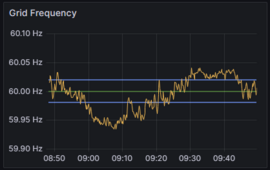
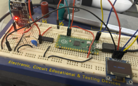
I’ve got one I built using a Raspberry Pi Pico that reads out to 10 mHz, but even that took a long time to find a good zero-crossing detector that was any good. Definitely a tradeoff between timebase and resolution.

I mean, it’s conceptually easy, just count zero crossings for 100 seconds. 😁🤓
 
If you are not able to find anything cheaper, iotawatt logs voltage and frequency, and can log it for up to three different sources.
 
Last edited:
Here is the code and the basic idea for the Raspberry Pi Pico grid frequency counter:
My test implementation has been stuck in breadboard form for, oh geez, 1.5 years now, lol, still working.
View attachment 204132
Nice, I’ll take a look, thanks!
 
Here is the code and the basic idea for the Raspberry Pi Pico grid frequency counter:
Interesting, but I think my "mini-industrial control panel creation" or wiring up speaker crossovers is about as low level as I want to get with with electronics. Maybe when I retire I might play around with this kind of stuff. Years ago I tried "make your own pcb kit". It didn't go well. I also built a heath kit amplifier. Someone who knew what they were doing had to fix it. Well one channel did work OK, and nothing blew up when I plugged it in, so I guess it wasn't that bad.
 
Here is the code and the basic idea for the Raspberry Pi Pico grid frequency counter:
My test implementation has been stuck in breadboard form for, oh geez, 1.5 years now, lol, still working.
View attachment 204132
Nice, I've gotta spend some time wrapping my brain around the Pico state machines and assembly language, but that's on me. What did you use for a zero-crossing detector?
 
Nice, I've gotta spend some time wrapping my brain around the Pico state machines and assembly language, but that's on me. What did you use for a zero-crossing detector?
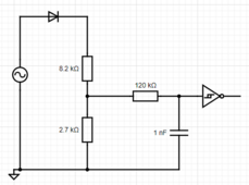
I had a 9V AC wall wart lying around. I cobbled this together - it's a half-wave rectifier -> voltage divider -> 1300 Hz low pass filter (because why not) -> schmitt-trigger inverter. (don't care about the inverting part but the hysteresis is helpful to avoid spurious transitions. If you're an analog circuit expert, feel free to laugh but you must then offer improvements. :cool:
1711406295673.png
 
I had a 9V AC wall wart lying around. I cobbled this together - it's a half-wave rectifier -> voltage divider -> 1300 Hz low pass filter (because why not) -> schmitt-trigger inverter.
A simpler solution is the 9 VAC signal through a 4.7 megaohm resistor to the gate. You don't need to divide it down, rectify it, or anything.

No, the 9 VAC voltage won't harm the gate because it has protection diodes and the current you push through such a high value resistor is minimal.

If you want a little more filtering, put a 47 pF cap on the gate input. 720 Hz low pass filter.

None of these circuits are true zero cross detectors since they have a time lag from the zero cross to the logic edge. But I don't think that matters for the purpose at hand. If you want a true zero cross, logic edge aligned with the actual zero, that takes more careful design.

Mike C.
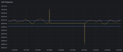
Thanks Mike! It's a great idea and easily testable since 1) this circuit is still in a breadboard and 2) I have 19 more 74HC14 chips just in case. Yeah I wasn't too worried about the exact trigger time since I'm averaging over 120 cycles it works out ok. I'm happy with the output - when the power goes out and my UPS takes over, the graph gets quite flat right at 60Hz:1711427257117.png
 
Interesting, just ordered one. Can’t wait to tear it apart and see how it works.
I didn't look inside them too much. They power themselves off the AC line they are monitoring. So there are only two input terminals on the frequency version.

I have the "Current" version of the devices already. You hook it up to the AC, but then it also has a little CT that needs to have the current wire stuck through it. It displays positive current values only. The CT is solid, not clamp on. The display itself is a small PCB about 1 inch in diameter with the LEDs installed on it. There is probably a counting circuit on the other side of the LEDs, but there could also be a second board underneath.
 
Last edited:
You can point a webcam at it and redneck yourself some logging.
I thought about that. It's sure much easier to read a data file and graph it than it is to look through hours of video trying to find what you want.

I'm going to add this gage to the cover of the control box. More cool lights to look at. It took me an about hour to decide on the color.

  1. Gee, the red one looks cool.
  2. I already have a red gage.
  3. I could use the white one.
  4. White is too boring.
  5. They also have Yellow.
  6. I don't like Yellow.
  7. Yellow doesn't mean anything in this context.
  8. Return to number 1 and repeat 500 times.
 
Last edited:
Back
Top