Kleazy
New Member
Background:
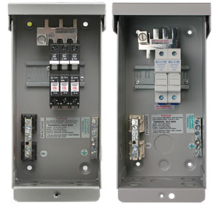
I am building a combiner box. The install is in a Central American country and there won't ever be any inspection by any authority hence I build as it makes sense more so than what is required.2 PV strings that will be combined in parallel inside the box.
Currently doing design research online here and on YouTube.
Many designs use a fuse for each string and then a double circuit breaker for positive and negative. It seems excessive.
And of course a SPD which I am a believer in.
Then I look at the Midnight Solar "minimalistic" approach of only fusing or circuit breaking the positive while the negative is permanently wired towards the charge controller.
Questions:
1. What does US code require for PV combiner boxes?2. What is the point of using fuses AND circuit breakers for the same circuit in series?
3. What is the advantage/disadvantage of protecting the negative end of the circuit with a breaker?
Last edited: