TomC4306
Solar Obsessive
Or just buy one ready made.


Thanks Tom, I appreciate the link.Or just buy one ready made.
Funny, after all the bad reviews it got just a couple of days ago. Skip the diodes, I run six strings in parallel without them.Thanks Tom, I appreciate the link.
I wanted to build one this time around so I can understand the system better.
I see in your signature you have 'Solar Assistant' running on a RasPi. It looks pretty slick, how have you found it?
I'm using Victron gear and have VenusOS running on a Pi attached to a 5 inch IPS display which sure beats paying 500+ USD for a Cerbo GX and GX Touch.
? Sorry I don't understandFunny, after all the bad reviews it got just a couple of days ago. Skip the diodes, I run six strings in parallel without them.
I read those too.Funny, after all the bad reviews it got just a couple of days ago. Skip the diodes, I run six strings in parallel without them.
So after doing a bit of soul searching I've decided to just buy a combiner box. There's not much savings to be had with a DIY job.Or just buy one ready made.
What was the gist of the reviews? Got a link? At first glance it looks like one of the less dodgy ones at that price range.Funny, after all the bad reviews it got just a couple of days ago. Skip the diodes, I run six strings in parallel without them.
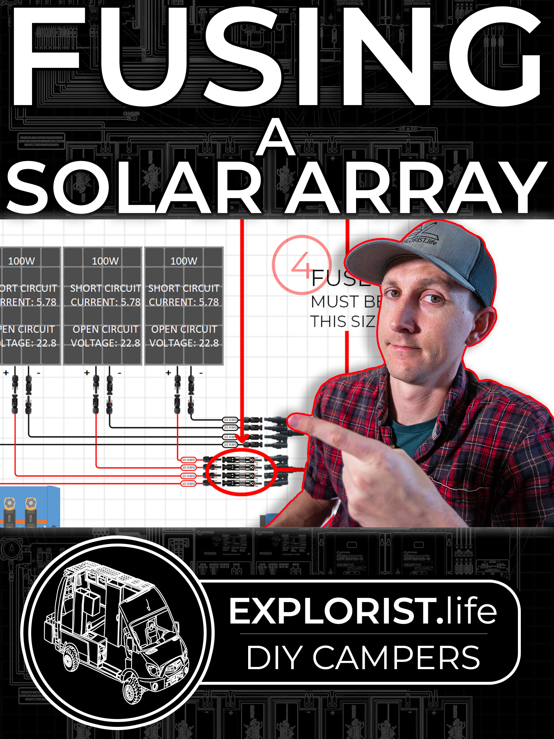
| Total number of PV panels | 8.00 |
| Total Open circuit voltage (Voc) | 90.8V |
| Total Short circuit current (Isc) | 21.56A |
 explorist.life

What?connectors, I can use a 4 string combiner box and save on the PV cable.
But do I then need 16x MC4 fuses?
Yeah there's no need for branch connectors at all that's my bad. Don't know what I was thinking. It helped to draw a diagram.What?
You have a total of eight solar panels, correct?
Each serial string should home run to the combiner box.
Panel1+ to panel2- , panel1- to combiner and panel2+ to combiner.
There is no need for branch connectors or mc4 fuses. The fuses are in the combiner box.
And, yes, you will need to buy wire to reach from where the solar panels are mounted to where the combiner box is mounted. So..... Mount the combiner box near the solar panels.
Total number of PV panels
Total Open circuit voltage (Voc) 99.88V
Total Short circuit current (Isc) 21.56A
From what I have gathered, a combiner box should consist of:
...
# SPD (Surge protection devices) also called TVSS (Transient Voltage Surge Suppressor)
1. The individual fuses should be rated at 1.25x total short circuit current of each string – in this case, 26.95A
2. We only need one fuse per string as only the positive is being fused
3. The SPD will do nothing if it isn’t hooked up to an earth (grounding rod)
1. Can the 2x individual fuses and the 2P switch be replaced with a single 4P circuit breaker? If so, are circuit breaker current ratings for each INDIVIDUAL input or is it a CUMULATIVE total
2. For the isolation switch, do we need to switch both positive and negative poles? Would we need a 2P unit or 4P
3. I can’t find the Maximum Series Fuse Rating on the panel spec sheet. Can we calculate it some other way?
Solar panels still have to use the wires in order to convey the short to another panel and if those wires go through a fuse right at the panel or through a fuse at the combiner box there's still a fuse on the wire from the panel to the other panels.Yeah there's no need for branch connectors at all that's my bad. Don't know what I was thinking. It helped to draw a diagram.
I think there are some cases where you still fuse BEFORE the combiner box in case one of the panels shorts. But thinking it through, the only time that's necessary is when you have 3 or more panels in parallel, so if one shorts then the other two can overload it. Or something like that.
That makes a lot of sense when you put it that way, if the circuit breaks anywhere it won't flow. Thanks for all your patience and input.Solar panels still have to use the wires in order to convey the short to another panel and if those wires go through a fuse right at the panel or through a fuse at the combiner box there's still a fuse on the wire from the panel to the other panels.
No need for two fuses.

100VWhat is max input voltage spec for your equipment?
Voc < 100V at 25 degrees C, but up to about 116V depending on how cold your location gets.
There currently isn't an inverter but there will be in the near future. The future inverter will be next to the batteries to save on wiring. The combiner box will be located inside the house for ability to isolate the panels by throwing the MCB when needed. What's the idea behind SPD's being closer to the inverter?Is box to be located at the inverters, or remote, at the array?
I think surge suppressors should be located at the inverters NOT at the array.
So that's multiplicative? And just using 1.56x is a quick way to do it?Fuse and wire ampacity should be at least 1.56x short circuit current.
That's 1.25x times 1.25x, one is for self heating of wires & nuisance trips, the other for cloud edge effects exceeding Isc.
No it won't be. I'll check the inverter manual when I purchase it. Fuses are cheap.Unless this is a transformerless grid-tie inverter. In that case I think both positive and negative are supposed to be fused; check the manual.
I'm not sure I completely understand this.SPD (e.g. MOV) across PV +/- could clamp differential voltage, which is where charge controller circuit resides. Some protection.
There are filter components to ground, so connecting ground rod or ground wires is useful.
SPD e.g. from Midnight Solar can be three MOV in a delta arrangement, PV+, PV-, ground.
Don't just put an earth ground rod at the array. You must run a wire from array frames back to inverter/charge controller. People get shocked when PV frames aren't wired to inverter.
Individual fuses for strings to not go over 15A and an MCB for the cumulative current of all the panels x 1.56. Got it.Each string needs OCP for about 15A. Either fuse or non-polarized breaker.
If a breaker for 4 strings in parallel, 5.39A x 4 x 1.56 = 33.6A; breaker needs to be at least that large.
If you do use 4x 2 pole 15A non-polarized breaker, then no need for breaker on combined wire.
Or, 4x 15A fuses, and one 35A or 40A breaker (either polarized or non-polarized.)
Do you have only one MPPT input? If two, you can run 2s2p into each MPPT and skip the fuses. Just have two 2-pole 20A breakers (polarized or not) as disconnects.
Yep, do it once do it right. Safety first.I think both poles should be isolated. Everything disconnected when you're working on wires.
Yeah I've just been down a rabbit hole regarding Maximum Series Fuse Ratings and come out the other side probably more confused than when I started. If we assume it's 15A MSFR on these panels, this set up wouldn't be over because none of the panels are paralleled. BUT if I had two of these panels paralleled, it would be over (5.39A x 1.56) x2 = 16.8ASurprised it doesn't say. With 5.39A Isc I'd expect about 15A max fuse.
Raw panel specs are in the image, that table you were looking at had a +10% safety factor on the voltage for some reason.
2S4P should be:
90.8V
21.56A
100V
Location doesn't get below 0.
I'll admit it's very close for comfort at 100V limit. What are your thoughts?
Would the panels being second hand have any impact on the voltage they'll put out?
There currently isn't an inverter but there will be in the near future. The future inverter will be next to the batteries to save on wiring. The combiner box will be located inside the house for ability to isolate the panels by throwing the MCB when needed. What's the idea behind SPD's being closer to the inverter?
So that's multiplicative? And just using 1.56x is a quick way to do it?
5.39A x 1.25 x 1.25 = 8.421875A
So I should be using this current safety multiplier everywhere from the panels on, up to and including the MCB fuse rating and the wiring between the MCB output and the MPPT input?
But not when sizing wiring after the MPPT for instance the MPPT to battery charging, just regular AWG charts for reference.
Cloud edge effect sounds cool, what does it like magnify the light or something and concentrate it?
I'm not sure I completely understand this.
I'll be putting a ground rod in for the eventual AC system anyway as I'll be using RCD's or RCBO's.
My takeaway from this is you are saying "Don't just earth the panel framing" ?
What do you mean when you say "Wire the frames back to Inverter/CC" ?
Individual fuses for strings to not go over 15A and an MCB for the cumulative current of all the panels x 1.56. Got it.
Would I get any extra protection or accidental tripping issues if the fuses were 10A and not 15A?
I only have a single MPPT input.
Yep, do it once do it right. Safety first.
Yeah I've just been down a rabbit hole regarding Maximum Series Fuse Ratings and come out the other side probably more confused than when I started. If we assume it's 15A MSFR on these panels, this set up wouldn't be over because none of the panels are paralleled. BUT if I had two of these panels paralleled, it would be over (5.39A x 1.56) x2 = 16.8A
Am I even anywhere close to understanding MSFR's?
Hey thanks so much for your input buddy, it's really helpful and much appreciated!
")
Is this the data you are working off? I assume TC 25° is what you were looking at. I don't know the relevant calculations but it's the one point of the system I'm not 100% about and it's so close to the 100v MPPT voltage limit that it gives me concern.I guess I focused on your 98 or 99V number, missed the 45.4 Voc per panel.
100/90.8 = 1.101, 10.1% margin.
Don't know the temperature coefficient of Voc (from your data sheet) but even if as high as -0.4%/degree,
10.1% / -0.04% = -25.3 degrees C. (relative to nominal 25C). That's good down to 0C, freezing.
I won't count on degraded helping, and you would have difficulty being sure of a measurement, need to know solar intensity.

The cable run will be about 5m from the roof to the combiner box/batteries/inverter.Twofold. If lighting current induces current in the home run wire, SPD at array anchors that to ground with low impedance. So voltage and drive current at inverter are higher than if no SPD.
If lightning strikes the ground and spreads out, it finds your ground rod, fires the SPD, and runs through PV wires to your inverter.
Either of these, I only think is an issue with a long run of wire, e.g. array at a distance or on the roof.
If this wire sizing is after the MPPT, would I not just use standard DC AWG wiring charts to size the wires for maximum MPPT SCC output and not need to multiply it by 1.56?Sized for maximum current MPPT SCC is capable of delivering.
If undersized due to small array, then do size it according to array x 1.56 and scaled to battery voltage.
In this set up I gather it's not an issue whether I use 10A or 15A fuses in the combiner box. Ideally 10A but nothing that should affect a purchase of a pre-built combiner box.That seems to be the idea.
You won't actually see 16.8A, might see 5.39A x 1.25 x 2. But the fuse might blow below 15A because it is getting hot in the sun, and wire to terminal connection adds heat.
If all 3 other strings dump their current into 1 string which is shorted, then I expect 15A fuse to blow in full sun. Eventually, they take time.
Wires can short due to mechanical damage. Bypass diodes can fail shorted, although I don't think all will (they get killed by current from others in series.) If you got a bunch of used panels, then maybe you could make one string with all shorted bypass diodes.
Thanks again Hedges, your a legend! I'll send you a picture when it's doneIf one PV string per fuse, 10A or 15A should be OK.
Between MPPT SCC and battery, fuse should be at least 1.25x max current rating of SCC. Wire ampacity should be at least as high as the fuse.
1.25x is to avoid nuisance blowing. Ampacity considers temperature terminals allow and equipment and fuses or breakers, which is often less than wire insulation rating.
If DC AGW charts say larger, you can do that.
The equipment can have a ground rod.
A wire needs to go from equipment ground to PV panel frames.
If panels are on roof and combiner + surge arrestors are on wall outside the house, electronics inside, that seems fine.
NEC or other rules may require RSD, GFI, AFCI for roof mounted panels.
Yes, Voc = 45.4V at ambient 25 degrees C.
I don't know the panels temperature coefficient, but probably -0.4%/degree or smaller.
That means down to 0 degrees C you don't exceed 100V. Below zero you could, unless temperature coefficient is smaller.
I think it is OK to touch 100V but never exceed it. That means use historical record cold, not recent low temperatures.