diy solar

diy solar

Combiner min fuse - Isc?

tonyg

New Member
Joined
Apr 5, 2022
Messages
136
Hi,

Quick one.
I'm looking at a Watts247 combiner box, but it comes with a 15A fuse... The Isc of my panels is 12.28A per string, isn't that a bit close? Max fuse says rating 20A on the panel sticker. I mean on a cold bright day, the VoC can be exceeded, can it be a similar situation for the Isc?

Cheers,
Tony
 
Yes, it is, and yes it can.

NEC specs call for wire ampacity and fuse at least 1.56x Isc
That's the usual 1.25x to avoid nuisance blowing, times another 1.25x for "cloud edge effect" when extra light reflects onto panel.

12.28A x 1.56 = 19.16A

A 20A fuse and minimum 12 awg wire is appropriate.

But you only need the fuse if you have 3 or more PV panels (or series strings) combined in parallel.
 
I thought so as well, but was challenged by someone online when I wanted different fuses in the combiner box (20A not 15A ones).
 
Yes, it is, and yes it can.

NEC specs call for wire ampacity and fuse at least 1.56x Isc
That's the usual 1.25x to avoid nuisance blowing, times another 1.25x for "cloud edge effect" when extra light reflects onto panel.

12.28A x 1.56 = 19.16A

A 20A fuse and minimum 12 awg wire is appropriate.

But you only need the fuse if you have 3 or more PV panels (or series strings) combined in parallel.
"But you only need the fuse if you have 3 or more PV panels (or series strings) combined in parallel." What if you have 2 series strings combined in parallel? Looks for some clarity for understanding. Thank you.
 
I've used a fuse anyways, even for two strings.
Made in the end my own combiner box, within an empty consumer unit box that has 20A fuses, a DC mcb and a surge protectoion unit. Then on top of the box, there's a disconnector.

All turned out nice and working perfectly!
 
I've used a fuse anyways, even for two strings.
Made in the end my own combiner box, within an empty consumer unit box that has 20A fuses, a DC mcb and a surge protectoion unit. Then on top of the box, there's a disconnector.

All turned out nice and working perfectly!
Same here. My 2 cents is that those y adapters are recipe for trouble plus future trouble shooting and reconfiguring is so much easier if you've got access to the individual strings.
 
This is something that I have never understood. My understanding is the Isc is the disconnected amperage, when zero current is flowing, and the Imp is the amount of amperage flowing when the unit is under load.

Since a fuse functions by the amount of current flowing through it and heating it to the point that it melts to break the circuit, then why is Isc used in the specification at all? Intuitively, I would have selected 1.25X the Imp?

No it isn't, but actually...

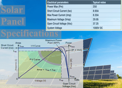
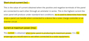
Isc is 'I' (current) 'sc' (@ short-circuit)...

Imp is 'I' (current) 'mp' (@ maximum power - @ the resistance point where volts x amps = highest watts)...


Ref:


EDIT:
So comparatively...

Voc is 'V' (volts) 'oc' (@ open-circuit)...

Vmp is 'V' (volts) 'mp' (@ maximum power - @ the resistance point where volts x amps = highest watts)...


1663272155762.png
 
Last edited:
No it isn't, but actually...

Isc is 'I' (current) 'sc' (@ short-circuit)...

Imp is 'I' (current) 'mp' (@ maximum power - @ the resistance point where volts x amps = highest watts)...


Ref:


EDIT:
So comparatively...

Voc is 'V' (volts) 'oc' (@ open-circuit)...

Vmp is 'V' (volts) 'mp' (@ maximum power - @ the resistance point where volts x amps = highest watts)...
The distinctions are a little blurry...
1663272132345.png
 
The distinctions are a little blurry...

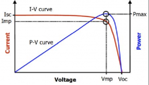
Refresh your page again and see the screenshot I added in my above post. The chart demonstrating a typical MPPT sweep curve will show it better.

EDIT:
As you pull the circuit down to full dead short (Isc), then volts comes down too as amps reaches peak, you have more amps, but eventually volts becomes too low to still be at maximum power point by then...

A solar panel is a very dynamic circuit. A fully relaxed circuit (open-circuit), sits at Voc, but no current flowing. MPPT sweep loads the circuit down (reducing resistance) and finds max power point watts and draws max charging power there when it needs the most battery charging. When batteries are fully charged, it relaxes the circuit enough to maintain float voltage on the charger side...

The only time Voc and Isc are seen in real world, are most likely only briefly, during the periodic MPPT sweep operations by the charger (or when the charger float is disabled or charger turned off might reach Voc), and even then, it may not even pull it down to a total Isc dead short, as it should (if designed properly), never pull it down all the way, or safeguards would stop it from pulling it down to a point where it could exceed a maximum and cause damage to itself.

However, many manufacturers will indicate a maximum Isc you can safely wire to (overpaneling on Isc amps), without risking damage to the controller. This is where it is not always clear in documentation, how far you can over-panel on amps, with all the various manufacturers.
 
Last edited:
It's generally understood by some, that the fuse or other over-current protection device (if installed), exists to protect the wire. If the wire is sized sufficiently large enough to not be in danger at Isc sum amperage, then you don't really need a fuse on a solar circuit (if you consider that the solar panels can be the only power source that can supply power through the PV circuit wires).

However, many people install a fuse to protect the wire anyways, perhaps supposing maybe a lightning strike could hit it and over-current the wire?

I put breakers / fuses on all my PV runs, just as good practice to protect the wires from potentially unexpected over-current, even though the solar circuit (at max Isc) will never be able to max out the PV run. Plus it's nice to have a quick disconnect (breaker) in case I need to service something down on the charge controller end of things (during the daytime).
 
Last edited:
"But you only need the fuse if you have 3 or more PV panels (or series strings) combined in parallel." What if you have 2 series strings combined in parallel? Looks for some clarity for understanding. Thank you.

If the only source for current is the two strings of panels, fuses sized for one string in each string will never blow. No matter where a short occurs, only current from one string flows through any fuse.

If a string shorted to ground and SCC somehow backfed battery into it, then fuses could protect an array with one or two strings. But generally it is said no fuses are required unless three parallel strings.

My transformerless GT PV inverters are supposed to have a fuse for every string. That is in case something fails and grid is fed to the string(s).

In other words, "It depends"
 

diy solar

diy solar
Back
Top