diy solar

diy solar

Compress or not, flexible busbar or not

@MrM1 Its not so much the density, its the ability of foam to push back, just like a spring.

Think of it as a spring, squash the spring, two months later when you release it, it will return to the same length, so its still exerting pressure.
If you squash most foams they will take a set, release it after two months and it stays squashed, so it stops exerting a pressure.

You also need to know how much pressure the foam exerts, and unless you can get a data sheet for the foam, you won't know.
 
Silicone is Approximately.045” thick. Went this way at first but changed my mind to Formica. 8AAE8386-A9E3-4F64-9667-560273E01ED6.png
 
The red colored, high temp silicon rubber pads is probably the best to use but it is rather expensive. It has a good durometer (optimum sponginess), is resistant to taking a compression set, and its high temp capability may help reduce likelihood of any adjacent cell thermal transfer cascade runaway.

Neoprene rubber takes a compression set over time, has a rather low melting point, and is a thermal insulator.

You don't want to use a material that takes a compression setting collapse under long term compression.

The idea pad thickness is when about 25 lbs/sq. inch of pressure compresses the pad 20-40% of its uncompressed thickness. This amount of compression stays in linear compressive force range. With the variability in cell surface flatness this will likely take a minimum pad thickness in the 1/4" to 3/8" range. The thicker the better, to hold uniform pressure across surface of cell and avoid pad taking an over-compression set.

The downside of all of this is you are reducing the cells' ability to dissipate any internal generated heat by wrapping two large sides of cell with a thermal insulating blanket. This partially defeats the original intent to reduce delamination of electrodes from metal foil due to high temp excursions.
 
Here we go again!

I tested the 0.25" Poron foam and found that one sheet per four cells is what you want to use for cells that specify ~12 PSI compression and up to ~0.5mm expansion per cell. I used one sheet in my four cell battery and two sheets in my eight cell packs.

I am confident that whatever slight imperfections the cell sides had when I started (it wasn't much at all) conformed as needed to meet the rigid separator and the next cell over.

Link to the actual test results:
https://diysolarforum.com/threads/a...this-time-about-foam.16537/page-4#post-530262

By the way, the EVE specification sheets seem to no longer talk about allowing expansion; they state an initial compression force of 300kgf at ~30% SOC and clearly show a rigid fixture. It seems that they no longer are concerned about "over compression."
 
Ofcourse they aren’t concerned about over compression or allowing for any expansion. They state X amount of cycles for a fixed compression and as long as the cells reach those cycles they are in the clear.
Allowing for expansion is a must imo. Mistakes happen. Overcharging, over discharging etc. allowing room for mistakes is good insurance. Also as we discussed before there is the possible extra pressure towards the end of cells life. allowing for this extra expansion/pressure could be a good idea.
 
Last edited:
I tried to find the fiberglass sheets like you see in the kits and they were too expensive.
Same experience when looking for pre-cut pieces. Finally, I found a local PCB manufacturer. They forwarded me to another local company that was making the materials they use. And I ended up ordering 2sq.m rolls and cutting them myself. For 3 16S batteries, the material cost was less than $50. The sheets can be cut with a utility knife.

Folks, talking about springs and Poron foam - which one is cheaper?
 
I won’t get into what’s better. Spring are $11 but I wouldn’t use it on more than 8 cells so you set up 3/16” less than max deflection so WHEN the cells grow you are still safe but had plenty of push to start with. The pusher should be made from two 3/4 ply glued together for a 1-1/2” approx total thickness. Fixed ends same. What’s the best? Foam or spring, I got no clue. 89CDD786-80C5-48F3-BF5E-30F1B7BD2B6A.png1BC6AD86-AED6-437D-A160-D9239BACE12B.pngBF22EF2A-AF1F-4F15-B38A-0FC10FFE60F6.png
 
For more cells Longer springs = more deflection. Many different things can be used for the end plates. I used 1/4” steel plates
 
Found my Material List

Eight Cell Compression Module
(lithium "Squeeze Box")
Fits most 272/320 Ah Prismatic LiFePO4 cells with allowance for .045" silicone or insulator.
spacers sheets on wide battery surfaces (9 places).
Home Depot 2' X 4' plywood Sheets, Radiata Pine 1/2"(.480) & 3/4"(.725) thick:
1pc Bottom 3/4" X 7" X 29-1/8"*
2pcs Sides 1/2" X 9" X 29-1/8"*
4pcs Ends 3/4" X 7"* X 8-5/16" (2per end)
2pcs Thrust plate 3/4"X 6-15/16" X 8-1/8"*
*Denotes surface grain direction. Doubled thrust plate has the only vertical grain.
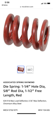
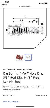
Ends sit on bottom and between sides. 1pc Spring, 634.6 LB @ .56" deflection
from MSC (mscdirect.com) PN 07661879.
1pc 3/8-16 four pronged Flange nut
1pc 3/8-16 X 3" Bolt, zinc plate (not stainless! it may bend)
1pc 3/8 fender washer, 2pcs 3/8-16 nuts
Grease for threads and washer surface.
Teks sharp point lath screws #8x1-1/4" to align while gluing.
Clamp up assembly squarely before gluing for test fit and fasteners. Drill tight clearance holes through first side
and pre-drill small hole for threads. Disassemble and glue up & screw tight.
Titebond 3 glue, re-coat edges after a few minutes soak in before assembly.
When done, protect with Minwax Helmsman Urethane 3 coats.
 
Ofcourse they aren’t concerned about over compression or allowing for any expansion. They state X amount of cycles for a fixed compression and as long as the cells reach those cycles they are in the clear.
Allowing for expansion is a must imo. Mistakes happen. Overcharging, over discharging etc. allowing room for mistakes is good insurance. Also as we discussed before there is the possible extra pressure towards the end of cells life. allowing for this extra expansion/pressure could be a good idea.
My take on the specification is that it is the manufacturer's statement of best practice. They have put a lot of effort into figuring out what works best, yet we continue to second guess. I do understand that the Chinese is not incredibly clear to most of us, but the instructions on how to make the rigid fixture are pretty clear.
 
The crazy thing is that the batteries are so expensive yet they usually don’t even include information pamphlets or links to specs like torque, compression charge rates, etc.
 
I think they just give the minimal amount of info. All they have to do is lead us to the specified amount of cycles. If we over charge/over discharge they don’t care if there’s to much pressure. That would be our own fault or bms problems. Having springs or poron foam is cheap insurance
 
Last edited:
This should put all these questions to rest...very detailed video from a German battery expert.

 
Anybody that doesn't speak German can turn on auto translate sub titles, or can watch the below video and see Andy's interpretation.

Agreed. But I'm curious why Andy did not mention terminal stress. In his 1st video about his swelling several days ago, his swelling appeared to be putting stress on his terminals.

I would think if nothing else a compression frame would help keep the expanding and contracting of the cells from placing stress on the terminals.
 
Just kinda wondering what’s going on inside some of the server racks after year. Welded on busses, snug placement and a supporting structure not designed for cell expansion restraint. Should prove interesting one way or another.
 
Agreed. But I'm curious why Andy did not mention terminal stress. In his 1st video about his swelling several days ago, his swelling appeared to be putting stress on his terminals.

I would think if nothing else a compression frame would help keep the expanding and contracting of the cells from placing stress on the terminals.
exactly my thought, and hence i will keep fixation.
the whole "more cycles" never had any bearing on that to begin with.
common sense tells me that expanding and contracting puts stress on terminals and busbars.
 
The way I see it, you either compress or leave space, like full end of buss bar slots kinda space. There is no in between. I however will continue to follow the manufacturer’s recommendations. In a few years we’ll know after many cycles how the rubbing of internal layers pans out.
 
Back
Top