diy solar

diy solar

connecting an inverter: spark prevention / reduction

pellicle

retired ex-professional dingbat
Joined
Feb 8, 2022
Messages
122
Location
Queensland, OzTrayLiYa
when I attach an inverter (turned off, unloaded) to my battery system there is an inevitable inrush of voltage to fill the capacitor. I wonder what is the best way to do this and reduce this spark. I've read of people using a 0.1Ohm resistor, which I assume is sufficient to slow it down. Before I get one, does anyone have any views on a 1ohm wirewound resistor for this task? (cheaper than a 0.1 ohm)

My intention is to make the connection using the resistor as a "probe" then follow through with the actual connector in short order.

Thanks
 
It's an inrush of current to charge the capacitor.
Your battery's internal impedance probably limits this current so you then have an RC ckt.

V ---R----|
...............C
................|
............ground

With an ideal battery instantly connected to a capacitor, the current would be infinite, for zero time, IIRC. It's called an impulse function.

Why is this short term, high current inrush a problem?

"My intention is to make the connection using the resistor as a "probe" then follow through with the actual connector in short order."

Called a "soft start".
 
1 ohm may be significantly lower than needed.
But ohm's law means that your battery voltage will help ID the correct resistor.

I've used both 4 and 50 ohm resistors
 
when I attach an inverter (turned off, unloaded) to my battery system there is an inevitable inrush of voltage to fill the capacitor. I wonder what is the best way to do this and reduce this spark. I've read of people using a 0.1Ohm resistor, which I assume is sufficient to slow it down. Before I get one, does anyone have any views on a 1ohm wirewound resistor for this task? (cheaper than a 0.1 ohm)

My intention is to make the connection using the resistor as a "probe" then follow through with the actual connector in short order.

Thanks
Just go to car store and get the 10 Ohms 10W ~ 25W resistor they sell to be used with LED lamp conversion. 12V/10 Ohms will limit the current to 1.2A if it is 12V system.
 
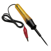
I just use one of these. The light bulb acts as a resistor. When the light goes from bright to dim or completely out you are good to go. Of course this applies to my 12 volt system.
1646112086709.png
 
Will has a video on this:


There is also the following in the Resources section:


And there are many existing threads on setting up a precharge resistor.
 
And there are many existing threads on setting up a precharge resistor.
Hi
perhaps its related to not knowing the appropriate key words, but when forming the topic many suggestions appeared. I ran through some of those and wasn't entirely sure of the limits
 
It's an inrush of current to charge the capacitor.
yes, you're correct. I should have been more carful in my words. I'm getting sloppy

I'm actually pretty familiar with this on another area, this is a blog post of mine from a few years back written to clarify why instructions on scooter / ebike charging were often mistaken
 
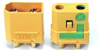
another option is XT90 plug with anti spark

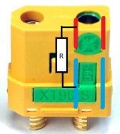
if it can handle the total current then no steps needed, since there is a precharge anti spark resistor built into the plug.

1646173476318.jpeg
1646173484512.png
this one is 5.6 ohm (green mark)

 
I watched Will on one of his Youtube videos. His recommendation was to use the resistor on the negative side?

I have always done on the positive side.

Does it matter?
 
I watched Will on one of his Youtube videos. His recommendation was to use the resistor on the negative side?

I have always done on the positive side.

Does it matter?
Mine's on the positive as well. It shouldn't make any difference. The whole idea is to complete a circuit with minimal current to slowly charge the capacitors.
 
I watched Will on one of his Youtube videos. His recommendation was to use the resistor on the negative side?

I have always done on the positive side.

Does it matter?
Is there an order to connect the DC power cables mentioned in the manual? Final connection gets the resistor.
 
I thought that was normal a big ass spark. Connecting my big outback 32v inverter its just pop! No way that big spark could be good for anything.

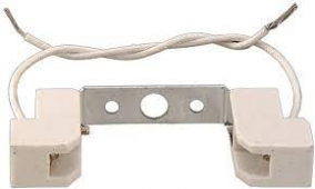
I am going to use a halogen lightbulb as a resistor. Got a crusty old work light, going to extract the socket and bulb mount on aluminum backing make it look cool like it belongs.

1660707234612.png


I don't think those marine battery switches are made to endure that spark that comes with turning big inverters on and off.

1660707950043.png


That seems about right, 5 olms.
 
1660708517484.png

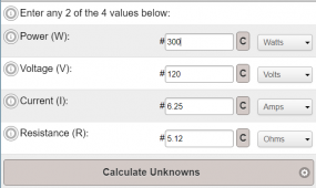
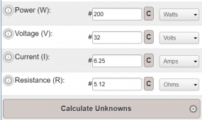
I plugged in 32v and 5.12 olms and got 6.25 amps. Any old switch can deal with that.

Guess I will put a momentary push button switch.
 
I thought that was normal a big ass spark. Connecting my big outback 32v inverter its just pop! No way that big spark could be good for anything.

I am going to use a halogen lightbulb as a resistor. Got a crusty old work light, going to extract the socket and bulb mount on aluminum backing make it look cool like it belongs.

View attachment 107217


I don't think those marine battery switches are made to endure that spark that comes with turning big inverters on and off.

View attachment 107218


That seems about right, 5 olms.
300W/120V = 2.5A, how does it get 6.25A?
So Hot resistance of the incandescent lamp will be 120V/2.5A = 48 Ohms, the Cold resistance (about 10 ~15 < Hot resistancce) will be about 4.8 Ohms, you can easily verify with Ohm meter. Incandescent lamp has positive coefficient.

BTW, when perform the pre-charge, make sure the power switch of the inverter is in the OFF position.
 
Last edited:
Mine's on the positive as well. It shouldn't make any difference. The whole idea is to complete a circuit with minimal current to slowly charge the capacitors.
Good practice to connect +ve first so resistor would be used on -ve. Battery -ve is often tied to earth or chassis. Dropping the -ve is much safer than +ve. Good example is jump starting a car. Almost everything in the engine bay is -ve so you don't want to drop the +ve lead in there!
 
Outback FX series no on - off switch comes with it. Its a wire in option. That I should do.

What happens bad if the inverter is on when charging caps with resistor ?
 
Back
Top