Peter Evans
New Member
- Joined
- Sep 7, 2021
- Messages
- 8
Hello All!
Setting up a basic 40 panel system with three separate 10 Kw inverters and (14) 5Kw batteries.
The battery manual shows they can be set in parallel and the batteries themselves have two inputs each for positive and negative. The batteries came with 4 AWG cabling to connect each battery to bussbars.
It also shows connecting the batteries from battery to battery in parallel using a different pair of 4 AWG wire that they also sent me with the battery purchase.
It seems to me that when you get to the 5th battery you are exceeding the ampere capacity of 4 AWG wire and the gauge would have to increase as you added battery after battery until you reached the maximum draw from the inverter, say limited to 250 amps.
So while the manual shows them accumulating 16 batteries in a long string of parallel connections wiring then going to the inverter, it seems like an error in the manual has occurred.
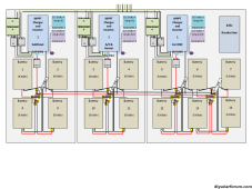
My current plan (see picture) is to connect four batteries in parallel (each with there own wires to a 300 amp buss bar (4 buss bars total) with one inverter connected to each buss bar.
So My Question: Is there something I am not understanding about amperage that would somehow allow the entire string of 14 batteries to be connected in parallel, battery to battery with 4 AWG wire drawing 250 amps as shown in the manual, or is the manual completely broken?
Thanks in advance for the help
Setting up a basic 40 panel system with three separate 10 Kw inverters and (14) 5Kw batteries.
The battery manual shows they can be set in parallel and the batteries themselves have two inputs each for positive and negative. The batteries came with 4 AWG cabling to connect each battery to bussbars.
It also shows connecting the batteries from battery to battery in parallel using a different pair of 4 AWG wire that they also sent me with the battery purchase.
It seems to me that when you get to the 5th battery you are exceeding the ampere capacity of 4 AWG wire and the gauge would have to increase as you added battery after battery until you reached the maximum draw from the inverter, say limited to 250 amps.
So while the manual shows them accumulating 16 batteries in a long string of parallel connections wiring then going to the inverter, it seems like an error in the manual has occurred.
My current plan (see picture) is to connect four batteries in parallel (each with there own wires to a 300 amp buss bar (4 buss bars total) with one inverter connected to each buss bar.
So My Question: Is there something I am not understanding about amperage that would somehow allow the entire string of 14 batteries to be connected in parallel, battery to battery with 4 AWG wire drawing 250 amps as shown in the manual, or is the manual completely broken?
Thanks in advance for the help