I didn’t wanna start another thread, but this arrived today. A touch over 1200 bucks delivered. It is used and is surplus but you would be hard pressed to show me that it was used past the initial setup time and the 1 hour twice yearly. The engine serial shows it’s a 2015. Apparently I can log into it via a Ethernet once I commission it, but 7.5 kw 48 volt dc for 1200ish sounds pretty good to me


You are using an out of date browser. It may not display this or other websites correctly.
You should upgrade or use an alternative browser.
You should upgrade or use an alternative browser.
Current Connected turnkey Micro-grid
- Thread starter Ahb1989
- Start date
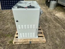
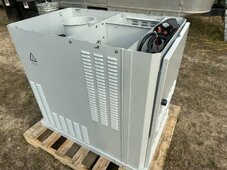

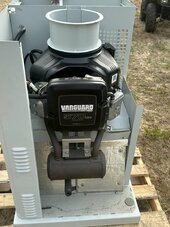
Did you get this DC Generator installed?I didn’t wanna start another thread, but this arrived today. A touch over 1200 bucks delivered. It is used and is surplus but you would be hard pressed to show me that it was used past the initial setup time and the 1 hour twice yearly. The engine serial shows it’s a 2015. Apparently I can log into it via a Ethernet once I commission it, but 7.5 kw 48 volt dc for 1200ish sounds pretty good to me
Will you be operating this in the Autorun mode?
Can you adjust the output voltage? Looks like it is set to 52.5V default.
I do have it installed currently.Did you get this DC Generator installed?
Will you be operating this in the Autorun mode?
Can you adjust the output voltage? Looks like it is set to 52.5V default.
The 52.5 default setting is a problem, one of which I haven’t decided exactly what to do about it.
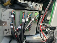
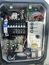
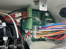
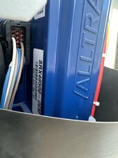
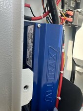
At first glance the system is controlled by a custom PLC and it’s locked except a user interface fed by a modem.
The system is obviously completely designed for lead acid batteries. I could likely adjust the governor and spin the voltage up a few points but one of the plc parameters is excess voltage so I would imagine that it would start a shut down sequence.
Also the auto run low is 48 volts which leaves enough juice to auto start but even the partially charge limit of 52.5 it would never turn off until 53 volts are met which wouldn’t happen until the solar or shore power charged above that threshold.
So I figure my options are try and adjust the plc parameters to allow modifications something I know nothing about. Find out of the generator head is adjustable at all or if rpm feed is my only adjustment and what the plc would allow to pass through.
A crazy thought I had was to use a chargerverter set to 5-6kw draw that’s controlled by an external controller powered by my existing inverter. Use the Sol-Ark generator contact switch connected to a solenoid to break the voltage sensing wire of the generator. The generator would then start on its internal batteries, output 7.5 kw ish until 52.5 volts, then figure out a way to make the charger run for a period of time to charge the batteries to 80 percent of what ever the number should be until the taper isn’t efficient.
Effectively I wish I would have bought the more expensive polar power that was listed that has a better controller but it was 8 times the expense.
I think I can make this unit work better with some kicking ideas around, but it has already saved my bacon once just by using the manual start feature.
If you want to charge 16S LFP, you need about 56.0 volts. That's about 6.7% higher than the 52.5 volt nominal. Probably within range to reach with some adjustments.
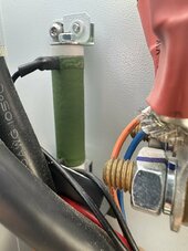
One way to "fix" this is to find the point at which the voltage is measured. It will be a resistor divider network that has an upper resistor and a lower resistor that converts the higher voltage into a level that the control circuits can convert digitally, usually on a span of 3.3 or 5.0 volts.
If you add some resistance to the upper resistor, you can make 56.0 volts "look" like 52.5 volts. That means the system will think it is producing 52.5 volts but it needs 56.0 volts output to do that.
Exactly where and how to make this adjustment is a circuit issue that would take some examination to find, but once located, the fix is rather trivial and doesn't involve changing parameters or software.
It is possible to also do more complex scaling such that what was 48.0 to 52.5 volts can become 48.0 to 56.0 volts. In other words, you can also play with the offsets with the proper resistor network.
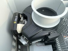
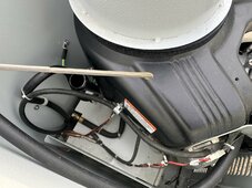
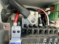
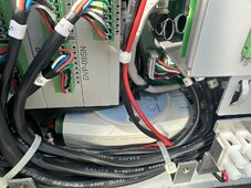
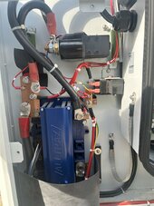
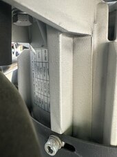
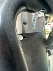
Do you have hi res photos of the electronics on the generator? That would provide a start for where to put in this adjustment.
Mike C.
One way to "fix" this is to find the point at which the voltage is measured. It will be a resistor divider network that has an upper resistor and a lower resistor that converts the higher voltage into a level that the control circuits can convert digitally, usually on a span of 3.3 or 5.0 volts.
If you add some resistance to the upper resistor, you can make 56.0 volts "look" like 52.5 volts. That means the system will think it is producing 52.5 volts but it needs 56.0 volts output to do that.
Exactly where and how to make this adjustment is a circuit issue that would take some examination to find, but once located, the fix is rather trivial and doesn't involve changing parameters or software.
It is possible to also do more complex scaling such that what was 48.0 to 52.5 volts can become 48.0 to 56.0 volts. In other words, you can also play with the offsets with the proper resistor network.
Do you have hi res photos of the electronics on the generator? That would provide a start for where to put in this adjustment.
Mike C.
Id love to work through this with you and anyone else on the board. Hardware this is an exceptional deal I think. It has automatic oil change option and runs very well, it's a no brainer if I can make it more Lithium friendly.If you want to charge 16S LFP, you need about 56.0 volts. That's about 6.7% higher than the 52.5 volt nominal. Probably within range to reach with some adjustments.
One way to "fix" this is to find the point at which the voltage is measured. It will be a resistor divider network that has an upper resistor and a lower resistor that converts the higher voltage into a level that the control circuits can convert digitally, usually on a span of 3.3 or 5.0 volts.
If you add some resistance to the upper resistor, you can make 56.0 volts "look" like 52.5 volts. That means the system will think it is producing 52.5 volts but it needs 56.0 volts output to do that.
Exactly where and how to make this adjustment is a circuit issue that would take some examination to find, but once located, the fix is rather trivial and doesn't involve changing parameters or software.
It is possible to also do more complex scaling such that what was 48.0 to 52.5 volts can become 48.0 to 56.0 volts. In other words, you can also play with the offsets with the proper resistor network.
Do you have hi res photos of the electronics on the generator? That would provide a start for where to put in this adjustment.
Mike C.
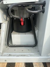
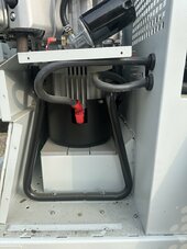
Your idea would work on the over and under PLC warnings, but wouldn't this have to assume the PLC is actually controlling the generator head voltage? Is that likely, or is it more likely that the generator head has its own built in regulator? I will grab some pictures of everything I can see.
Id love to work through this with you and anyone else on the board. Hardware this is an exceptional deal I think. It has automatic oil change option and runs very well, it's a no brainer if I can make it more Lithium friendly.If you want to charge 16S LFP, you need about 56.0 volts. That's about 6.7% higher than the 52.5 volt nominal. Probably within range to reach with some adjustments.
One way to "fix" this is to find the point at which the voltage is measured. It will be a resistor divider network that has an upper resistor and a lower resistor that converts the higher voltage into a level that the control circuits can convert digitally, usually on a span of 3.3 or 5.0 volts.
If you add some resistance to the upper resistor, you can make 56.0 volts "look" like 52.5 volts. That means the system will think it is producing 52.5 volts but it needs 56.0 volts output to do that.
Exactly where and how to make this adjustment is a circuit issue that would take some examination to find, but once located, the fix is rather trivial and doesn't involve changing parameters or software.
It is possible to also do more complex scaling such that what was 48.0 to 52.5 volts can become 48.0 to 56.0 volts. In other words, you can also play with the offsets with the proper resistor network.
Do you have hi res photos of the electronics on the generator? That would provide a start for where to put in this adjustment.
Mike C.
Your idea would work on the over and under PLC warnings, but wouldn't this have to assume the PLC is actually controlling the generator head voltage? Is that likely, or is it more likely that the generator head has its own built in regulator? I will grab some pictures of everything I can see.


Attachments
-
 IMG_3763.jpeg148.4 KB · Views: 8
 -
 IMG_3765.jpeg292 KB · Views: 7
 -
 IMG_3764.jpeg174.6 KB · Views: 7
 -
 IMG_3768.jpeg150.5 KB · Views: 6
 -
 IMG_3767.jpeg333.4 KB · Views: 6
 -
 IMG_3766.jpeg266.8 KB · Views: 6
 -
 IMG_3769.jpeg264.8 KB · Views: 6
 -
 IMG_3762.jpeg153.1 KB · Views: 6
 -
 IMG_3759.jpeg215.8 KB · Views: 7
 -
 IMG_3760.jpeg290.7 KB · Views: 7
 -
 IMG_3761.jpeg155.1 KB · Views: 9
 -
 IMG_3758.jpeg126.3 KB · Views: 9
 -
 IMG_3757.jpeg126.1 KB · Views: 8
 -
 IMG_3756.jpeg123.4 KB · Views: 7
 -
 IMG_3755.jpeg173.8 KB · Views: 7
So I got to playing with this thing today. I can adjust the no load voltage up to exactly 55.978 +- .014 without it throwing a critical error by a simple running speed adjustment. When I engage my battery bank and inverter with no ac loads I drop to 52.9 of course because they are charging.
I will be slightly under 56 volts with no work needed how will this affect my SOK charging on overcast days?
This still won’t allow my auto start to work but I think with some controller voltage adjusting as Mike C stated above the plc could be tricked into allowing it to start and stop normally.
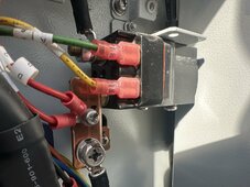
Over 56 volts the contactor opens on the dc solenoid and closes a few seconds later. It tries a few times then ultimately shuts down if the voltage doesn’t come back down.
I will be slightly under 56 volts with no work needed how will this affect my SOK charging on overcast days?
This still won’t allow my auto start to work but I think with some controller voltage adjusting as Mike C stated above the plc could be tricked into allowing it to start and stop normally.
Over 56 volts the contactor opens on the dc solenoid and closes a few seconds later. It tries a few times then ultimately shuts down if the voltage doesn’t come back down.
Last edited:
Your sure this only goes to 52.5 volts? That is 2.19 volts/cell for lead acid which isn't nearly high enough to charge a 48 volt lead acid battery. You need around 56.4 volts (2.35 volts/cell) for that to work, which makes a 16S LFP pack just about right.
Have you run the generator and seen what it actually outputs?
Mike C.
Have you run the generator and seen what it actually outputs?
Mike C.
There isn't that much LFP capacity between 55.5 and 56.2 volts, maybe like 3% or so. So if you adjust it to 55.5 volts (to give you some margin and drift tolerance), then it should charge your batteries pretty well. Not going to max voltage can also make your cells last a bit longer.Over 56 volts the contactor opens on the dc solenoid and closes a few seconds later. It tries a few times then ultimately shuts down if the voltage doesn’t come back down.
That seems like the simplest way to make this work.
Mike C.
What is the issue with autostart?This still won’t allow my auto start to work
Mike C.
Untouched this generator outputs 52.5 vdc with a drift tolerance listed of .5. I was able to confirm via dvm 52.5 is it. After adjustment I can pull a reliable no load 55.75 more or less. With a load I can go further of course but I think I would then error out if the batteries charged up enough to then be over volts of 56 .What is the issue with autostart?
Mike C.
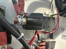
When I took all the service panels off for you today I figured I would play with the running speed some. Upper tolerance is circa 56 before the relay is opened.
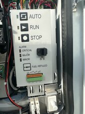
Natively the auto start is programmed to only start running at 48 volts, and it turns it self off when telecom cabinet reaches 53 volts. The theory appears to be that at 48 batteries are depleted enough to warrant the start, and 52.5 would run forever until the telecom chargers started back up and brought system voltage to 53 which would imply shore power was working again and the generator would then switch back to standby.
I don’t think the telecom people actually cared about the batteries being charged by this generator. It was more of an alternative power source when the backup batteries were depleted and they would be charged back by the shore chargers.
Weird other question. Inductively I’m only showing about max 50 amp draw dc when the generator is running with pretty discharged batteries.
7.5kw/56 volts should be a lot higher amp draw right?
That won't fully charge a 48V lead acid battery, but perhaps that wasn't the intent.Untouched this generator outputs 52.5 vdc
Well, that might be what you want, actually.Natively the auto start is programmed to only start running at 48 volts, and it turns it self off when telecom cabinet reaches 53 volts.
I don't think you want the generator to run so long as to fully charge the battery. It is sufficient for it to charge the battery up "enough" to keep the system running, and then turn off and let the system run on battery power. If the battery depletes down to 48V, start up again. You don't want to waste fuel going to 100% SoC if the sun will do that work for you later.
A 16S LFP reaching 48 volts is 3.00 volts per cell and is nearing the end of charge but still well off the safe end of 2.5 volts per cell. So that makes a pretty good generator start trip point.
At 53 volts, that is 3.31 volts per cell and LFP is decently charged at that point, enough that turning off the generator might be okay. It could stand to be a bit higher, maybe 54 volts, but not much higher.
When the sun comes out and you have solar, then the batteries can be charged to the max SoC. This saves the most fuel.
Exactly. Generator was there to prevent shutdown, not so much to replenish the batteries, though they would do that to some degree and cycle on and off.I don’t think the telecom people actually cared about the batteries being charged by this generator. It was more of an alternative power source when the backup batteries were depleted and they would be charged back by the shore chargers.
They may have designed the system to run at a particularly efficient operating point which was less than full power.Weird other question. Inductively I’m only showing about max 50 amp draw dc when the generator is running with pretty discharged batteries.
7.5kw/56 volts should be a lot higher amp draw right?
Or your setup just can't eat more power than the 50 amps.
Try just running it as it is and see what you get when tied to the battery bank. You might find that it does the job well enough and saves fuel over any other configuration. The telecom folks are not dummies so they probably know a lot about keeping such things operating efficiently.
Mike C.
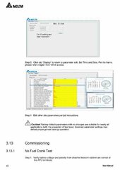
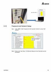
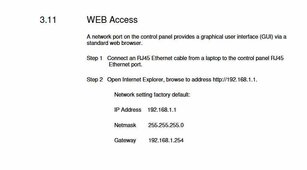
Have you tried connecting to this generator with a computer?
The User Manual pg38-40 shows how to connect.
setting numbers 21 and 22 has something to do with voltage calibration. I am thinking maybe you could trick it to put out higher voltage this way.
Then wire in the Remote disable terminals to SolArk GenStart contact normally close, to force the gen to stop when batteries are charged.
Attachments
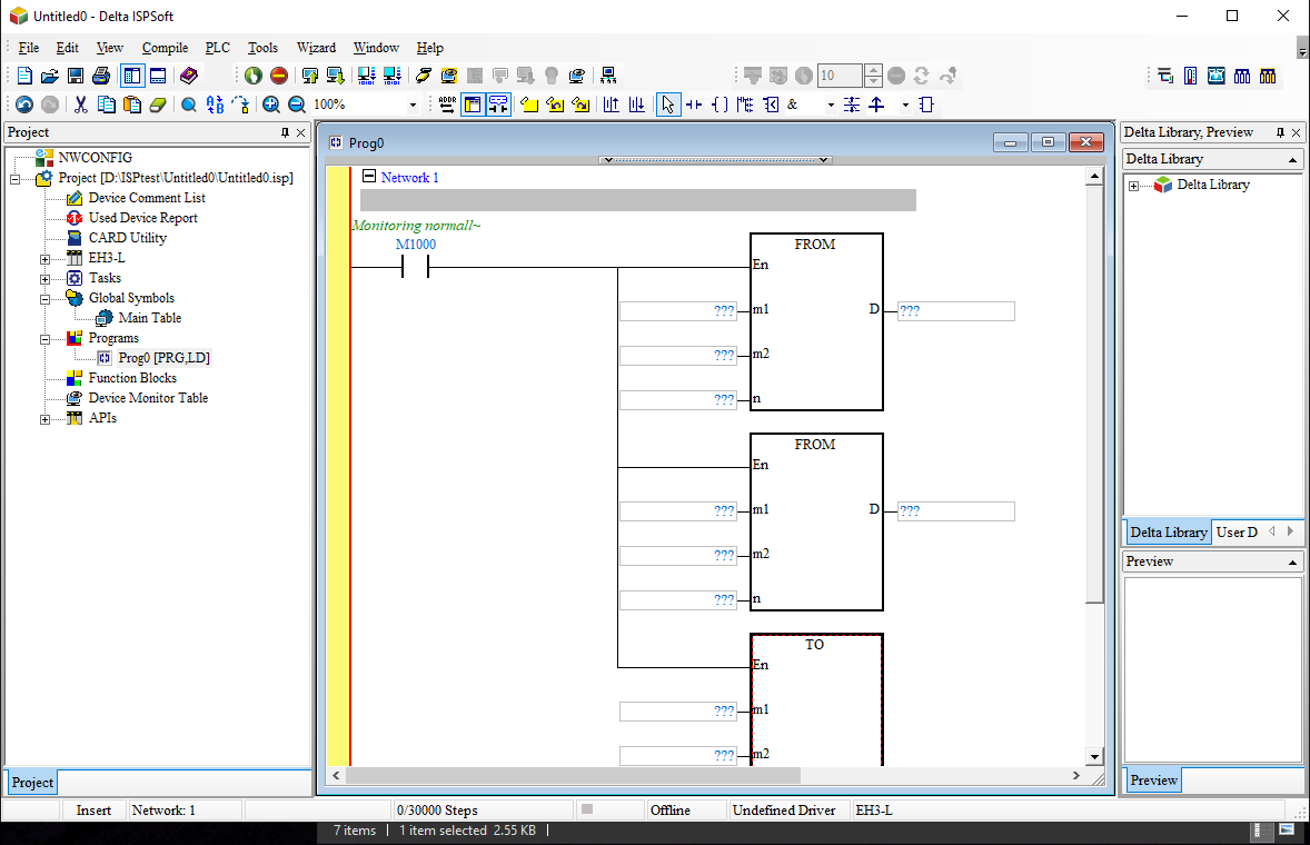
Have you tried connecting to the PLC with Deltas ISPSoft programming software?At first glance the system is controlled by a custom PLC and it’s locked except a user interface fed by a modem.
Download and Install Delta PLC Programming ISP Soft - Motive Automation
Motive Automation introduces itself as one of the fast-growing Engineering Firms that offer industrial automation and A-Z Electrical Solution. PLC-SCADA, Products, Software Development (PC-WEB)
I haven’t done any software change trials yetHave you tried connecting to the PLC with Deltas ISPSoft programming software?
Download and Install Delta PLC Programming ISP Soft - Motive Automation
Motive Automation introduces itself as one of the fast-growing Engineering Firms that offer industrial automation and A-Z Electrical Solution. PLC-SCADA, Products, Software Development (PC-WEB)www.motiveautomation.com
ScrotpusGobbleBottom
Corn Pop was a bad dude.
That is so awesome! THAT makes me want rack batteries.
12-Slot Outdoor Insulated Battery Rack - Fits SOK & EG4 Batteries | Current Connected
This new SOK 12-slot rack has built-in slots for heaters and/or AC units, allowing for easy control of the temperature inside the rack. With a sturdy design, it is easy to attach inverters on the outside for easier installation. Specifications: Outdoor rated enclosure (NEMA 4) that holds up...www.currentconnected.com

cs1234
Solar Wizard
- Joined
- May 9, 2022
- Messages
- 2,915
@HighTechLab
How about letting it be used as some type of solar mount ballast when used outdoors. Add some connection points for solar racking.. instead of just using air conditioning to cool it, how about shading it with a canopy of solar panels?
Either give it connection points on the side / top / front for panel racking.. or give it some type of sled add on that it can sit on, that has mounting points for panel racking that goes up above it / around it?
It certainly looks like it would be heavy enough to hold panels down when loaded with batteries. Forget using buckets full of rocks for panels, use this thing full of batteries and inverters.
HighTechLab
AKA Dexter - CTO of Current Connected, LLC
- Joined
- Sep 23, 2019
- Messages
- 1,796
That's a good idea. I'm going to reach out to some folks that make some solar racking and see what we can build off this.@HighTechLab
How about letting it be used as some type of solar mount ballast when used outdoors. Add some connection points for solar racking.. instead of just using air conditioning to cool it, how about shading it with a canopy of solar panels?
Either give it connection points on the side / top / front for panel racking.. or give it some type of sled add on that it can sit on, that has mounting points for panel racking that goes up above it / around it?
It certainly looks like it would be heavy enough to hold panels down when loaded with batteries. Forget using buckets full of rocks for panels, use this thing full of batteries and inverters.
Brucey
Solar Wizard
I forget the link but there was a place selling racking that used ibc totes as ballast which is similar to what you have thereThat's a good idea. I'm going to reach out to some folks that make some solar racking and see what we can build off this.
Found it
IntegraRack IR-G Series Adjustable Solar Module Racking Systems (MOQ: 10 Units) – Solar Power Distributors
 solarpowerdistributors.com
Similar threads
- Replies
- 3
- Views
- 489
- Replies
- 4
- Views
- 625
- Replies
- 3
- Views
- 1K
- Replies
- 16
- Views
- 774
- Replies
- 2
- Views
- 408