@Sanwizard I'm not disputing their quality, just their 1000A claim.
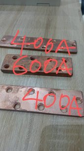
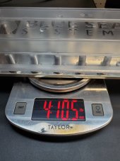
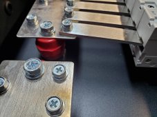
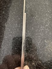
In the picture below on the left is a 40 x 8mm tinned copper bar, on the right a Bussmann JJN-400 T class fuse for comparison, the bolt in the lug is 8mm (5/16").
That bar is two finger widths, which is twice the width of yours presuming we have the same size finger
")
40 x 8 in imperial measurements is 1 and 9/16" x 5/16". Imperial measurements are just so messy.
Going by the link that
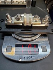
@Danke posted earlier, my 40 x 8 copper bar is rated at 721A. 40 x 8mm (320mm2 )is near enough the same cross sectional area as a 1/4 x 2" bar (25.4/4)*(2*25.4) = 322.58mm2. But I notice in
that link they have the cross sectional area as 636.6cm2 which is most odd.
View attachment 134073