Can anyone advise?
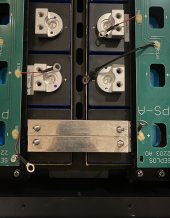
Background: I'm using LF280K EVE cells with the new double terminals, and as the EVE busbars or the ones provided with the mason aren't long enough to bridge the gap between the two rows I bought nickel plated copper bar from China planning to make my own.
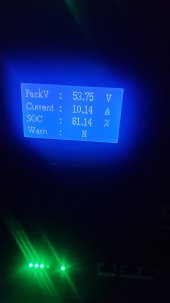
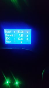
The busbars provided by EVE seem to be 20mm x 2mm so I ordered the same in nickel plated copper bar, unfortunately what arrived does not appear to be 2mm thick. And even if it is it isn't as thick as the EVE busbars. Would it still be OK to use? Or do I need a plan B? How many amps would it need to be able to safetly carry?
Am I overthinking this? I have some 70mm cable left over. Should I just stick some lugs on it and use that?