diy solar

diy solar

Daily BMS vs JK BMS

torstein

New Member
Joined
Sep 2, 2022
Messages
62
Hello.

Today I have a jk bms. As far as i have seen jk bms does not support setup in paralell. And the Deye Inverter do not support it out of the box.

When looking at daily bms its look like a different world of opertunities like the system they have to build big Banks?


What bms do People here use?
 
JK can be used in parallel setups. In such a configuration, ultra-fast Class-T fuses are required for each battery pack, to protect the remaining "active" BMS from sudden and dramatic over-current after another BMS (or two, or three) has already shut down after detecting excessive current on their battery packs. As far as I know, a parallel set of battery packs using ANY brand of BMS is subject to the issue (I own and use both JK and Daly).

Imagine 2 parallel packs, each with a "200A" BMS, configured to allow nearly the entire 200A on a continuous basis. Those BMS units can typically survive an overload of about 350A (+/- a pretty big variance from one brand to another) for the very short period of time which it takes the output circuitry to be fully disabled. But suppose that you have an extremely large Inverter, capable of pulling more than 400A on the DC input side if run "harder than you planned":

The load will not be perfectly even on the two battery packs, because no one can wire parallel packs that perfectly, and the internal resistance of the cells and BMS units varies from one pack to another. The BMS of one pack with more than 200A of load may operate correctly, with the output shutdown circuit disconnecting the load (with no BMS damage) after a short delay. But after that occurs, the remaining pack will be subjected to the full load (400A, maybe even more). It may already be in the process of disconnecting due to overcurrent itself, but it does the job a bit slower than the first pack. It is momentarily subjected to the 400A+ current load, output MOSFETs and detect/disconnect circuits can be burned out.

The purpose of the Class-T fuses is to protect the BMS units before the BMS can be burned out (by overcurrent or short circuit). DALY is not immune to the issue in banks of parallel battery packs, they just didn't bother describing it.
 
I have two 174AH + three 280AH in parallel, all using JK-BMS B2A24S15P. Wire lengths are identical and each has a 200A MRBF fuse at the Busbar. All packs are synchronized and operate within 00.01 Volt of each other and are well balanced between the packs.. When fully charged the cells in the packs are usually >0.005 delta between them.

The 174's are actually used EV LFP Cells while two of the 280's are "B" Grade and the last 280 is A Grade. I am now finishing a 24V/105AH Utility Pack for the toolshed Solar System, also with an identical BMS.
 
What if the packs are different ampere?
You will need to increase the resistance of leads going to the smaller pack, in order to obtain a decent balance in discharge and charging during the middle range of SOC. Mixing packs of different sizes is generally a bad idea, because it is VERY HARD to configure the lead wires to assure current values which are roughly proportional to the pack sizes. "Similar Packs" would be much better.
 
Sorry to disagree BUT All my Battery to Busbar, to E-Panel to Inverter wire is Royal Excelene 4/0.
There is 106A Difference between my packs (That is pretty much the limit that can work).
EndAmps/Tailcurrent is set to 8.5A (for the smaller packs).

Always use the smallest packs EndAmps. The math: 100AH x 0.05 = 5A EndAmps

In FACT, the batteries within the bank charge & discharge proportionately relative to their capacity. The larger 280's output more amps than the 174's when under load and take more amps when being charged compared to the 174's. The Bugaboo is when the packs reach about 20% SOC, the 280's will try to back charge the 174's. I've set the BMS to Low Volt cutoff @ 2.700 and they've never gotten there.

FYI: When my Midnite Solar Software says I am at 75% SOC (Uses their own WizBangJr SmartShunt) I can wander into the powerhouse and check the BMS' which all match and show as 75-78%. The BMS' are 3 decimal place accurate while the Midnite gear is only 1 decimal accurate. (Originally designed for Lead Acid, so 1 decimal acuracy was okay)

Royal Excelene 4/0 Specs.
AWG/KcmilCount# x AWGmilinchlb/1000ftAmp
Stock NumberCond. SizeCond. NumberCond. StrandsInsul. ThicknessApprox. ODApprox. WeightAmpacity *
104184/012052830.695773405

Have a look at this thread, it's in my signature but many cannot see our signatures and miss out on a lot of goodies.

PS: I have been running the 2x174's & 2x280's for 4 years. Started with Chargery BMS8T & 300A DCC's and QNBBM-8 Active Balancers and converted everything to JK BMS this spring and brought pack five online just recently as part of my Powerhouse revamp.
 
You will need to increase the resistance of leads going to the smaller pack, in order to obtain a decent balance in discharge and charging during the middle range of SOC. Mixing packs of different sizes is generally a bad idea, because it is VERY HARD to configure the lead wires to assure current values which are roughly proportional to the pack sizes. "Similar Packs" would be much better.
Will had a video with batteries of different capacities and this was not what occurred.
 
You will need to increase the resistance of leads going to the smaller pack, in order to obtain a decent balance in discharge and charging during the middle range of SOC. Mixing packs of different sizes is generally a bad idea, because it is VERY HARD to configure the lead wires to assure current values which are roughly proportional to the pack sizes. "Similar Packs" would be much better.
Understand. So if you have one pack that are 300a and one that is 500a. There will alwais leak power to the smaller pack
Not true. I have 2 Batteries in parallel and are both JK BMS managed.


I have Deye inverter with those two batteries.
I am running them without BMS communication without problem.

still no problem
Jusst set to manual voltage?
 
Jusst set to manual voltage?
You can have Deye use Batt V.
However LifePo4 voltage changes when charging/discharging/resting making Time Of Use not be reliable.

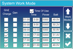
I mean, take a look at this Time Of Use (in voltages) example from Deye manual:
1664746617269.png
First line 01:00-05:00, Deye will stop inverting (supply power) when Battery dips below 49.0V.
But after a few minutes, battery will recover a few millivolts and be >49V again.
1664747110380.png
Deye will start inverting again and then drops down. rinse repeat with longer gaps.
Time Of Use does not have Hysteresis to prevent this situation.

This is where using Batt % is advantageous with Time Of Use.

From my observation with Deye:
1. Deye keeps track of your Battery's SOC internally by adding SOC% when charging, and deducting SOC% when discharging.
2. Unfortuantely Deye suck at keeping track of small flow, this drifts ~1% per day.
3. This internal count resets when battery disconnects: Resets to 0% when UVP and resets to 100% when OVP. This means, if you can fully charge your batteries at least once a week, you can be assured Deye's SOC% count will be fairly accurate for the week.
One method to guarantee full charge battery (once a week) is using Time Of Use: Set one day to conserve battery (set all Battery levels to 100%), allowing the next day to fully charge batteries..
But if you are already using Time Of Use for other stuff, then this method is a no go.
 
Last edited:
Understand. So if you have one pack that are 300a and one that is 500a. There will alwais leak power to the smaller pack

Jusst set to manual voltage?
No, there wil not be leakage to the smaller pack during discharge. But loads should optimally draw current from those battery packs in a ratio of 3/5, and recharge should apply current in approximately the same ratios. Without careful tuning of total resistance on the paths through each pack (terminal lead-in cables, BMS, and cells themselves), a different ratio may occur in practice.

With other types of batteries (e.g., SLA) the battery pack with lower State-Of-Charge will have lower voltage, and more current will be drawn from the higher-charged battery. But with LFP battery packs, the voltage is nearly constant through most of the SOC range (from around 20% to around 90%), and only the Voltage Drop occurring from resistance along the path will "tune" one battery to be favored over the other.

If your total discharge falls below 20%, then SOC will again become pretty well correlated with battery voltage, and the higher-SOC pack will begin to supply a larger portion of the current demand. And in charging above about 90%, both packs will become equally charged - again due to lower pack voltage pulling more current into the less-charged of the two packs, until they reach the same voltage levels.

The MID-RANGE of SOC is where LFP battery packs of different sizes (and possibly different BMS units adding different amounts of resistance) will fail to discharge and charge in a "fair" manner, unless you are very lucky (or have tuned the lead cable resistance to make it "more fair").

I hope that this longer post is understood better than my short one.
 
If the application was very high discharge/charge, then there would tend to be balance issues between various Ah size batteries. However, with a solar application where discharging/charging is not a high current application, the batteries will remain in balance if the cabling is done properly with busbars.

The idea is to limit voltage drop across the circuits to each battery, not to create resistance in order to "balance" the parallel batteries. With a SCC charging to constant voltage, similar to top balancing individual cells in parallel, the batteries will all reach the voltage the user sets in the controller.
 
Back
Top