diy solar

diy solar

Daly Parallel Module

jontm

New Member
Joined
Nov 24, 2021
Messages
39
Hi!

I am investigating into options for a offgrid hybrid application. It is an application where i need as much capacity as possible, but don't have the resources to purchase as big of a pack as i want this year. I want the option to expand the battery pack with lithium packs later on. The pack i am considering purchasing is 16 kWh (repurposed EV battery) and uses a Daly Smart BMS. I see that Daly now offers what they are calling Parallel modules as accessories to the Daly Smart BMS. I guess the idea is to have some sort of active balancing between the parallel battery packs to improve safety and battery life, at least that is my guess.
Will such a module enable me to for example add a 9 kWh battery pack in a year or two as long as the battery chemistry is similar and series configuration is the same ?
Anybody know if the Daly Smart BMS has the DO connector for the "parallel module" built in or if i need a special edition Daly Smart BMS to get this compatibility with the "parallel module" ?
 
Daly parallel module is to limit current between packs, no balance. It has a communication port which has to be connected with Daly BMS parallel port. So special BMS with parallel port needed.
Every pack parallel connected has to have parallel module.
 
I am assuming this current limit is just for the initial battery connection when two packs are at different voltages? I would think connecting them with a resistor and allowing the voltage to equalize would eliminate needing to have the parallel modules. Anyone have experience with that?
 
My thought exactly. One bms is not communicating with another, so there is no point to buy this custom bms when you can just get the battery voltage close to 50-100mV and them connect.
 
J'utilise les modules parallèles de Daly sur tous mes packs de batteries avec en plus l'égaliseur actif
J'ai changé tous mes BMS ANTS car ils ne fonctionnent pas en parallèle et ont grillé plusieurs cellules de mes
batteries . J'ai fait une vidéo sur la mise en place du module parallèle en Français si cela peut vous aider.
 
I have four 16S-batteries in parallel: three 200Ah with DALY BMS 100A and one 105Ah with a DALY BMS 60A. Each has its own DC breaker just in case. Each battery also has its Hankzor Balancer. They behave and play nicely together. I monitor them in 60s time frames and have them running for more than a year now. I sometimes do see current going back and fourth but this is in the range of one Amp. However I hardly stress them. They get charged with 30A max (which they divide up between themselves as they need it) and I hardly ever draw more than 50A in total.

When I need to take one down for service, I make sure to reconnect it either at the same battery voltage (down to 0.1V difference by charging the serviced battery) or via a resistor (which usually takes quite some time and produces heat).
 
They behave and play nicely together.
Great, thanks for confirming that.

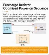
I had a look at some of the industrial battery rack BMSs and they normally have a pre-charge circuit consisting of a resistor and MOSFET to pre-charge inverter input capacitors and it also allows them to disconnect batteries when connected in parallel if the resulting current is too high without risking a massive current by switching on the MOSFETs.

Seems like the Daly parallel device is specifically for the case of battery-powered bikes being able to quickly add a temporary battery for range extension where the voltage levels will be substantial. Given the size of the parallel box and lack of a heat sink, I suspect they have a buck power supply with a current limit in it to essentially charge the other battery that is at a lower level (I think I saw 10A as the limit somewhere).
 
You hit the point, HateGRid, with your analysis of industrial battery packs but you are mislead with your assumption of the DALY solution assuming all the magic is within the add-on unit.

What I picked up from one of the AliExpress pages are the attached two pictures. One shows an inside to the parallizer as I call the add-on-device, the second the additional circuitry within the BMS (as I assume). So the DALY approach seems to be to have a quick exchange between the parallizer (they communicate via BT, so they might talk to each other as soon as they "see" a sibling). During this, each parallizer tells the others its battery voltage and depending one this, each one decides to switch on the pre-charge functionality in the BMS (picture 2) or not. The one with the lowest battery voltage will stay connected directly while the ones with higher battery voltage open S1 and close S2 in picture 2 hence limiting their respective discharge current. This is my assumption and may not be correct!

I thought of one such thing for myself if my system would get problems due to high loads resulting in different discharging levels within the paralleled batteries. I thought of disabling either the charge or the discharge MOSFET (figured out the respective communication commands for DALY BMS - see other thread). But this is a much more elaborate thing to do under high charge or discharge events and I have to think about it much more. Also there might be the need to react INSTANTANEOUSLY as within milliseconds huge amounts of energy could be shifted over.

That's why DALY might have opened a separate port on the BMS for the parallizer. Furthermore, the switching in the DALY BMS can take place BEFORE connecting to a battery, because they parallizers might have agreed via BT on who has to switch before any metals meet.

DALY Parallizer.jpgDALY Parallel BMS.jpg
 
Nice image captures.

I thought of disabling either the charge or the discharge MOSFET
You will end up with power being dissipated by the body diode of the MOSFET that is off, so you have to make sure the heatsink can handle the thermal load.

Also there might be the need to react INSTANTANEOUSLY as within milliseconds huge amounts of energy could be shifted over.
I would suspect that most over-current (short-circuit) circuits are hardware based (instead of microprocessor based), so should be in the nanosecond or microsecond range which should safely allow the MOSFETs to disconnect before they are damaged. Of course, every BMS design is slightly different . . .
 
Yes, the body diode heat dissipation is the weak point of this idea ...

Any idea on the hardware-based control of the MOSFET switch?
 
Any idea on the hardware-based control of the MOSFET switch?
Some MOSFET drivers (e.g Infineon 1ED44176N01F) have over-current protection included as long as you feed it a current signal from your current shunt circuit. The other option is to use a current sense amplifier (e.g. INA228) that has an alert output which you can use to disable the MOSFET driver or run into your microprocessor and shut it down. Just make sure your code is robust with a watchdog and fail-safe mode. If you have a really fast ADC in your microprocessor, you could do it that way, but you are looking at around 1 MHz sampling rate which excludes a lot of chips.
 
Last edited:
Puh, I am an Arduino level programmer and was not planning to develop my own BMS ...

Furthermore, when I can predict my charge/discharge currents, I do not expect to have huge problems with body diode power dissipation. This is because if leaving a high load status (i.e. switching back to more or less high charge status) and different batteries have different voltages (due to different wire resistors or cell aging), I just need to disable the discharge MOSFET for all but the weakest battery. Reason behind that is that all load changes will be covered by the charge current and if a discharge spike occurs, the weakest battery will jump in. But as to be expected, a high load status will remain for the foreseeable future, all batteries chime in depending on their battery voltage (weakest first, then second and so on). That way, there will be no current through the body diode of the discharge disabled BMS - if I switch each battery back on as soon as there is a small charge current (indicating that this battery will not discharge in a weaker battery anymore).
Same goes for getting into high load status although the batteries will be busy then anyway.

Hope, this does not go too deep into details ... maybe we better switch to PM.
 
You may be overthinking it. You only turn the BMS MOSFETs off for protection for over-voltage, under-voltage, and over-current. You also typically instruct the inverter (over CAN or RS-485) what the charge current and voltage will be to prevent over-charging and a minimum SOC where it will shutdown. This means that as long as everything is working correctly and your balance circuit is keeping all cells equal, you never turn off the MOSFETs in the BMS.

The parallel battery issue is only a problem when first connecting batteries packs to the system where a mismatch in SOC can cause excessive current flow between batteries. After everything is connected in parallel, the battery packs should all self equalize.
 
Last edited:
Well, I hope, I overthink it, but I am not sure, hence the discussion here ...

My line of (over-)thought: As I do not have 100% identical batteries plus the connecting cables are slightly different, this all adds up to different series resistors (differently aged cells, connector resistance, wire series resistance, ...). In a high-load-event, i.e. drawing a significant discharge current, these different series resistances will lead to different battery voltages (as only at the common joint the resulting voltage is equal). This might be differences of only few milli Volts, but as soon as the load current goes down, these differences "meet" at the common joint. Depending now on the inner resistances, these different battery voltages will create equalization currents. Depending on these differences, these currents can get big too. But yes, this might be a self-stabilizing effect as the same series resistances kick in. So the resulting equalization currents might just be a fraction of the load current that caused the voltage differences.

What is your opinion on that?
 
Once battery packs are connected in parallel, the current flow due to loads should be self balancing.

Weaker cells will have a higher internal resistance and will hence have a lower current flow compared with stronger cells. Cables should ideally have equal resistance, but if they do not, then the battery packs with a higher resistance cable will end up providing less current to the load so their SOC will be higher as the bus voltage drops. However, once the SOC drops below about 20% SOC (around 3.2V for LiFePO4 chemistry), the battery packs with the lower-resistance cables will drop in voltage faster than the higher-resistance cables and the packs should balance out.

For each battery pack of series cells, matching and balancing of the cells is much more critical since a weak cell will force an under-voltage disconnect early for the weak cell even though the other cells may be fine.

Simple summary: don't worry about parallel battery packs much other than when initially connecting them in parallel since they will sell balance between each other. Do worry about cell matching and balancing of series-connected cells within individual battery packs since a low cell compared to the rest causes the entire pack to get disconnected due to undervoltage.
 
Thanks for the soothing words. I am well aware of the issue with weak cells in a battery pack and I also follow your thoughts regarding low SoC behaviour. My worries are around the moment a high load switches off and equalizing currents run from high series resistance batteries to those with low series resistance (as the latter are deeper discharged during the high load time).
 
The current flow will not be that great in that case, do not worry. I have different chemistry batteries in parallel and the currents flowing are insignificant, compared to the high load ones.
 
Hello All,

I am paralleling multiple(2/4/6) battery packs for an off grid system with Daly parallel module+ smart BMS+ communication board. The final system should communicate with the Inverter through CAN. Let me know if anyone of you has figured this?
 
I am also running three 16S packs in parallel with each a Daly Smart BMS 250A - without any parallel module from Daly.

I wrote a tool to read out the data from the BMSes with a 10-second time interval and "merge" the data together to a single "virtual battery". The data is then pushed via MQTT to the inverter system (Victron), which only sees 1 single battery. More info on my setup here: https://community.victronenergy.com...services-creates-dbus-services-from-mqtt.html

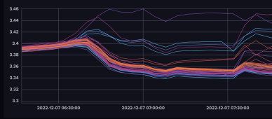
When SoC reaches near 100%, some cells typically "run away" and quickly rise above 3.45V - while others still are at 3.35V-ish. With this setup, it is possible to detect those "runners" and tell the inverter to stop/decrease charging - to prevent overload those cells. If I only looked at the total voltage, this would not be possible to detect and some cells would probably get damanged (or the BMS cuts-off).

See attached graphs of all cell voltages as SoC reached 99%
 

Attachments

  • Screenshot 2022-12-07 at 14.07.12.png
    Screenshot 2022-12-07 at 14.07.12.png
    213.1 KB · Views: 15
Last edited:
Back
Top