diy solar

diy solar

Damage to LiFePO4 battery during short-term moderately freezing temps???

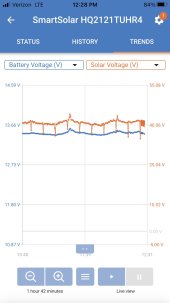
Sorry, I got “distracted“ by other “life” challenges. But, don't know if the battery healed itself, or if it’s just trying to fake me out, but installing a new fuse (on battery positive cable) has enabled/allowed battery to charge normally…I think. however, the controller showed solar voltage dramatically dipping (in half) momentarily once every 10 minutes or so…very consistent, like a metronome. So I still think something is weird. But, the battery voltage was steady (eventually rising to expected absorption voltage, then dropping to expected float voltage, at which point the BMS cuts amperage to zero (I believe it’s the BMS doing this).

SOO, when I can focus on this again, I want to “upgrade” the fusing, and would like to know how to best do this. Is there a thread or two that helps with this? Again, no inverters, no high current (when things are operating normally). But I think the way I was fusing this (cheap inline ATC fuse on positive cable) allowed the circuit protection to partially fail (the Fuse appeared to have turned into somewhat melted ”resister”26117E09-A707-4088-8F52-3872DAF48C53.jpeg….WHY? I have no idea).
 
unless advised otherwise, I am going to start a new thread…focused on getting help with proper fusing/circuit breaking.

again, current thinking (no pun intended) is that the Battleborn battery did not fail. A cheapo eBay or Amazon inline fuse did. Why, I don’t know, but the fuse melted, along with the holder itself. Oddly, the fuse melted in such a way that it continued to provide continuity…albeit at only a very low amperage (high resistance, I believe). So my new theory is this high resistance connection faked the controller out into thinking the battery was full. Replacing that inline fuse entirely appears to have corrected the problem. But it was a “short-term” fix, meant for diagnostics only. I WILL replace this fusing with more appropriate.

Of course I could (still) be wrong, and apologize that I began resisting advice. And, as far as I can tell, the “pulse” every 10 minutes or so has not reappeared.
First you need to know max amps on you wiring harness then find a wire gage that will handle that amperage if your near the max of the wires capacity 85% or more I would recommend next larger size

as far as the fuses size them to protect your wiring if the wire size requires a fuse that is not available size to the next available fuse going up in amps

go with a mega or Anl type fuse with holder they will hold up well
 
Low cost 'car audio' fuses and breakers on Amazon and eBay are very unreliable. Use link fuses with crimped eye cable lugs.
The regular 'dip' in solar performance is possibly the MPPT controller carrying out a maximum power sweep.
 
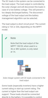
Just saw this thread, and want you to confirm the load terminal on the victron is rated for 20A.

The /20 in their name is the max charging rating, not the load rating.
Some scc load is .5A some are full battery output.
Victron is quality equipment, but your comment about it being the reason based on the 100/20 name has me concerned.
 
This is the YT video I wish someone would do. Torture test LiFePO4 server rack and 12v batteries under controlled situations of heat and cold and see how they behave and manifest damage..
 
Just saw this thread, and want you to confirm the load terminal on the victron is rated for 20A.

The /20 in their name is the max charging rating, not the load rating.
Some scc load is .5A some are full battery output.
Victron is quality equipment, but your comment about it being the reason based on the 100/20 name has me concerned.
Someone did a lot of testing on the load output, they found that you have to watch the inrush current demand otherwise the scc will protect itself.


And if running in 36V or 48V mode, the limit is 1A.

Screenshot_20230326_085109_Gallery.jpg
 
I had plans to include a diagram of my setup if/when I start a new thread, but got delayed (again). I’ve had it pencilled on paper
for 5 years, but it needs cleanup before publishing, and a way to point to where I want to upgrade the fusing (the pencilled diagram didn’t note any of the original fusing).

So I'm leaning toward an MRBF fuse at the battery positive, with perhaps a 80 or 100a rating (and 10k AIC from what I’ve read). 6awg wire would go from the MRBF to a secondary circuit breaker or fuse. That 80-100a MRBF ought to protect 6awg (right??). The idea behind the 2nd breaker (or fuse) is the 2nd would be readily accessible, so I don’t have to remove a drawer unit or crawl under the van if only the 2nd one tripped (which should trip first since it is smaller, except in case of battery short circuit). I’m thinking it could be 25a CB185-25 breaker or 30a MAXI or MIDI fuse. From this CB/fuse, the circuit goes to a switch, and then to the Victron. The switch is a NKK S-823D DPDT, rated at 30a @ 48VDC or less (still 15a @ 125vdc I believe).

so, the MRBF’s should protect the 6awg wires, and the smaller CB’s should protect that switch and the Victron…or at least that is my “theory.”

there is more to all this, but let’s start with this. IS THIS (above) A SOUND APPROACH?

OK, here’s where it gets hairier. I have 2 “strings“ of batteries. Gasp!!

So that would mean at least 2 of these MRBF’s (One string is 2x93ah AGM’s in parallel, assuming that would need only 1 MRBF fuse??; the other string is a single 100ah Battleborn LiFePO, which would have its own MRBF fuse). The 2 strings are sufficiently isolated IMHO, though ALL negatives are bonded. That switch I mentioned controls which string (positive) is connected to the Victron. Before anyone goes into convulsions about this 2-string approach, let me point out I’ve had it for 5 years, living in this van for months at a time…just not with Victron, and not with LiFePO until a year ago. It worked fine all summer, but something happened while “parked“ for the winter off-season…which is what brought us to the original point of this thread.

well, one more thing, I believe the 20amp output of the Victron is adequate for my loads, and as Brucey pointed out, the 20a limit appears to apply to both charging and 12v loads…but this is a frequent criticism of my approach. That and the 2-battery-string concept. Maybe if I were starting greenfield, I would ditch the 2-string approach, but it’s saved my bacon more than once, when 1 string became exhausted, or had issues like what caused this thread in the first place. I simply switched the switch, and was back in business, in this case, using the AGM String. I also would have been smart to have bought the Victron 100/30 instead, which has more robust terminals, though lacks the load out connections. But I was getting a bit tapped out ($$$) buying the Battleborn, a bigger 250w solar panel, and the Victron. The older Morningstar (PWM 15a) never hiccup’d, and I used its LVD load outs as well, but I appreciate having more charging and storage juice now. I’m no doubt just plain lucky the cheapo fuse didn’t inappropriately melt before.
 
Last edited:
Back
Top