diy solar

diy solar

DC Breaker acting funny, dropping voltage

MartyByrde

Off-Grid Innovator
Joined
May 16, 2022
Messages
151
Location
USA
Hi,

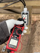
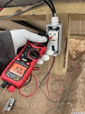
I am using DC circuit breakers for the first time and I’m having some confusion about the voltage. I have 12 250 W used solar panels from santan solar wired in series. It was a cloudy day and they were measuring around 150-230 V with the DC circuit breaker switched off. It’s my understanding that this would be the VOC. When I switched the breaker on the voltage dropped to 40-50V.

My inverter has a PV MPPT voltage range of 120–550 VDC. I haven’t connected it to batteries yet and it wouldn’t turn on today from just that 12 string of panels.

Is there something wrong with the DC circuit breaker for the voltage to drop down that low, or the voltage wasn’t high enough to meet my inverters minimum requirement?

Lastly, when I turned the DC circuit breaker on and held the multimeter on it for a about a minute it seemed to almost be “charging up“. The voltage began to rise gradually from a lower number and just kept climbing. I’ve never seen this before. Any thoughts?

I have yet to ground the panels to the grounding rod, but just wanted to get the inverter up and running to make sure it works.IMG_7093.jpegIMG_7094.jpeg
 
so just trying to get this clear. Your inverter which i assume has a solar charge controller in it. It was not hooked up to the battery when you were trying to send power from the panels to it?
 
Measure the voltage across just the positive pole of the PV breaker and see if you are getting more than a volt or two dropped, if it is the difference between input and output then there is your problem. Repeat test on negative Pole.
The voltage seems rather low for a string of 12 panels so I would also be double checking all of the connections.
And finally mppt do vary the voltage depending upon the load, so for example if your battery is full and there is nowhere to put power your PV voltage will rise to the full VOC of the panels but whilst charging a battery that voltage will be quite a bit lower as it pulls way more current.
 
Went back and tested each panel. Figured out that it was a bad MC4 connector that was messing up the whole string
 
Went back and tested each panel. Figured out that it was a bad MC4 connector that was messing up the whole string
Well done - that's good binary troubleshooting.

But ... one thing to take from this is that if you have any active gear downstream of your breaker (lets say a SCC), you are not gathering much (any?) good data by testing the top and bottom of the breaker in the on and off positions. The reason is that if the SCC is faulty (open circuit), then you should see array-voltage on the top of the breaker and nothing on the bottom when the breaker is OFF (expected), and array-voltage on the top and the bottom of the breaker when the breaker is ON (also kind of expected).
However... if the SCC is faulty (short circuited), you will see array-voltage on the top of the breaker, and nothing on the bottom of the breaker when the breaker is OFF (to be expected) but you will see almost nothing on the top, and almost nothing on the bottom, when the breaker is ON (due to the short circuit dumping almost all voltage across the SCC. This will look (to the inexperienced) like a breaker fault
Usually after replacing the breaker 3 times with known-good breakers, the inexperienced will click!
Also, lets say your SCC is fast at MPPT calculations, has an empty battery, and rapidly starts pulling the voltage of the array down to get to the MPPT point - in this case you will see the voltage drop, which can look very much like a poor terminal or faulty MC4 when in fact its just normal operation. If the battery is full and the SCC is in float, it will be drawing almost nothing from the panels, so you might be expecting to see a drop from Voc down to Vmp, but you wont see this if the SCC is idling.

Bottom line: Be wary of voltage-only data on a breaker - it can mislead you, and a voltmeter plus a clamp (so you know voltage and current at the same time) will help you more easily make sense of things.
One interesting thing I found is that my inverters MPP LVX 6048 WP have 2S2P inputs and are able to parallel the strings at the inverter PV inputs (each PV input has 2 positive and 2 negative to connect the individual strings, and the inverter is programmed to parallel.). Some of the paralleled strings would still show voltage on the bottom side of the breaker from the other paralleled string for the DC breaker that was off. So voltage was feeding up from the one string and down back through the wires out to the other DC breaker. I’m not sure if this is normal but seems like it might be something that is unsafe, or require a second DC breaker to break the connection.
 
Back
Top