I am a bit puzzled by this.
Thank you all for your replies , I will check again
Hi so I did as you said,
My PV panels now produce 330V~ open circuit at full sun .
I only have connected the fuses on the inverter's PV inputs .
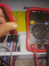
I measured the voltage on the inverter's PV input ( with no battery or PV panels, just the inverter with fuses on the PV inputs ) and it shows 0v both directly and before/after fuse. I do the diode test on the PV inputs + - and its 0.4V one way , 0v the other way, both directly on the inverters inputs and the fuses outputs.
0.4V is the expected reading when applying polarity that would conduct through the diode; diode clamps voltage to protect inverter from reverse polarity. I don't know if fuse holder and wire to inverter is exposed so you can trace it to inverter, or not. You touched inverter's input, not fuse holder?
Which inverter terminal did you put red DMM wire on when you saw 0.4V, the positive or the negative? Do that again with red DMM wire on the fuse holder you think is same (positive or negative).
If red wire is on positive fuse holder when you read 0.4V, that would see to mean fuse holders (or your understanding of which goes to positive inverter terminal) is wired backwards. If on positive terminal of inverter when you read 0.4V, I'm confused.
As for 0V, I didn't expect that. I expected "overload" or similar message. What does the DMM say if you just touch DMM leads together? What does it say if the DMM leads aren't touching anything?
(For all DMM I've used, the red test lead, plugged into positive terminal of DMM, sources positive voltage in ohms or continuity or diode-test scale. For those of us who grew up with analog meters having needles, the positive lead sourced negative voltage because they simply put a battery in series. I think DMM reverse polarity of display to be more intuitive.)
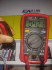
I connect the inverter with lead acid 24v , I get an arch on the batterys terminal , and it turns on , immediately, the inverter still is OFF position . I measure the voltages on PV input its 9V now, I do the diode test and its 0.4V one way , 0v the other way, both directly on the inverters inputs and the fuses outputs.
If PV input says 9V (and polarity matches your expectation) it isn't shorted. All bets are off as to what diode test shows when measuring something that sources voltage. We avoid measuring resistance of live circuits.
Then I turn the switch to ON position and the inverter 230V output kicks in. I measured the voltage on the AC OUTPUT and it says 230V so everything is working great with just the battery. Now the voltage between the PV inputs is not 9v but 20V, both on inputs directly and before/after fuse. I do the diode test and its 0.4V one way , 0v the other way, both directly on the inverters inputs and the fuses outputs.
Some of them do leak voltage onto the PV terminals, even high enough to shock. So always disconnect other sources and verify voltage has decayed low before touching.
The I measured continuity on the PV inputs and fuses and everything is OK.
Is there a test I missed ?
Here is Will showing a similar inverter . He just connects the high voltage solar panels directly during daylight with mc4 to the inverter without battery and it works.
I also ordered a Schneider circuit breaker DC 600V.
I know I could try without fuses but what if somehow the inverter is shorting the PV panels and I start fire connecting the mc4 ? The manual explicity says you should use DC switch breaker and it doesn't go much into detail why or when ( I can post a photo of the manual if you want ).
With rated breaker and not the burnt fuse holders, you can safely close and open breaker with PV attached.
With breaker closed, measure voltage across inverter PV input terminals. Observe polarity.
If it read something between 0.4V and 2.0V, I think that means it is reverse polarity. So look for that.
Some people on the forum have wired PV backwards.
But I don't get that 0V reading on diode check scale. Maybe it has to do with your particular meter.


") Hagar) says "do not operate under load"...
Hagar) says "do not operate under load"...