mrzed001
Voice of reason
Not a joke 
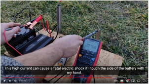
Here is a little video with measurements demonstrating it:
In Hungarian language, but in a browser you can turn on subtitles and set it to Auto translate to English

What you see is a simple setup. From left to right
First test:
Second test:
Third test (with the previously grounded system):
Fourth test (with the previously grounded system): Current measurement
Fifth test (with the previously grounded system): Current measurement
The reason is: the inverter is a NON ISOLATED inverter.
There is no isolation between the AC part and the DC part.
And so the AC part will be present in the DC side.
Andy run into this problem too, but did not investigate it further.
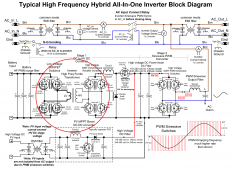
The All-in-one inverters are usually isolated to battery
The big red circle is the isolated DC/DC converter in the MPP Solar like inverters

Also I want to mention that the MPPT (below the circle) is NON ISOLATED.
This is the reason you should not ground the PV cables in these systems.
That would mean immediate AC short circuit.
Here is a little video with measurements demonstrating it:
In Hungarian language, but in a browser you can turn on subtitles and set it to Auto translate to English

What you see is a simple setup. From left to right
- 12V battery
- 230V EU style inverter (Line - Neutral = 230V), 500W (2,1A). A really small inverter
- Ground rod
- RCD 30mA. The blue Neutral is connected to the PE cable (the bond). Not connected to ground rod first.
- A second ground rod representing a Person
- Multimeter for current measurements
First test:
- Inverter works, L-N: 202V (small inverter
)
- Line to Ground: 0V.
- System is not grounded.
Second test:
- PE (bonded to N) connected to Ground rod.
- N-Ground: 0V
- L-Ground and L-Person: 202V
- RCD test successful, RCD disconnects
- It is a grounded system now
Third test (with the previously grounded system):
- Battery terminal - Person : 104Vac
Fourth test (with the previously grounded system): Current measurement
- Battery terminal - Person : 0,7A = 700mA (from the inverter's max 2,1A)
- If he would touch the battery terminal ... that could mean lethal shock.
Fifth test (with the previously grounded system): Current measurement
- Battery terminal - Ground rod : AC Short Circuit (sparks)
- Inverter stops working
The reason is: the inverter is a NON ISOLATED inverter.
There is no isolation between the AC part and the DC part.
And so the AC part will be present in the DC side.
Andy run into this problem too, but did not investigate it further.
The All-in-one inverters are usually isolated to battery
The big red circle is the isolated DC/DC converter in the MPP Solar like inverters

Also I want to mention that the MPPT (below the circle) is NON ISOLATED.
This is the reason you should not ground the PV cables in these systems.
That would mean immediate AC short circuit.


![300 watt MSW Power Inverter Schematic].png 300 watt MSW Power Inverter Schematic].png](https://diysolarforum.com/data/attachments/113/113820-cd6af6f9139360b8134a9cccb49f7b12.jpg)