diy solar

diy solar

Debunk: Alternator DC to DC charger not required for big Lithium Battery

The voltage drop is what limits the output but it is the current that creates the drop. When the battery is low, the current will be max and on my coach is self-limiting to about 60A. once the battery gets closer to full, it quits taking so many amps and the voltage drop is less.
To put it a different way, if my LFP batteries need to be charge, I will get 60A and the voltage at the LFP will be 13.0 to 13.4v. If I am coming off the campground and the battery is full, the current to the battery will be nil and the voltage will be 14.4v. No current = no voltage drop.
Just to confirm do you have any lead acid batteries in this system?

I'm confused about a couple things. Is the voltage drop from wire length limiting the batteries ability to pull current or is it simply the wire size limiting the current? If it's the wire size isn't it getting severely hot?

If it's the wire length and voltage limiting the current it seems like your entire system is relying on the alternators regulator to be at that specific voltage. If this failed and voltage ramped up even a little it could cause all kinds of issues.

I was under the assumption that lfp pulls all the power it has available at all times until it's full.
 
Just to confirm do you have any lead acid batteries in this system?

I'm confused about a couple things. Is the voltage drop from wire length limiting the batteries ability to pull current or is it simply the wire size limiting the current? If it's the wire size isn't it getting severely hot?

Can be both. When wire length is the predominant component of resistance, the higher resistance limits current, and it stays well within wiring limits. Additionally, a long wire has a lot of surface area for cooling.

If the alternator "sees" 14.4V when the battery is only at 13.6V due to voltage drop, it's going to limit output current.

If it's the wire length and voltage limiting the current it seems like your entire system is relying on the alternators regulator to be at that specific voltage. If this failed and voltage ramped up even a little it could cause all kinds of issues.

If the alternator regulator fails, you're going to have problems anyway. A suitably sized fuse can protect the system and allow normal operation.

I was under the assumption that lfp pulls all the power it has available at all times until it's full.

Generally speaking, compared to lead acid it does, and it does almost all of its charging in the 13.2-13.8V range. but when the equipment that's feeding it has limitations, there is less current available.


@ 45' length (one way), 2/0 has a 1.89V drop @ 270A thus, the alternator will see 14.4V when the LFP battery is at 12.51V, which is nearly empty, so it will start tapering its output to less than 270A once the battery hits 12.51V. This assumes all connections are perfect.
 
[Q1] Just to confirm do you have any lead acid batteries in this system?

[Q2] I'm confused about a couple things. Is the voltage drop from wire length limiting the batteries ability to pull current or is it simply the wire size limiting the current? If it's the wire size isn't it getting severely hot?

[Q3] If it's the wire length and voltage limiting the current it seems like your entire system is relying on the alternators regulator to be at that specific voltage. If this failed and voltage ramped up even a little it could cause all kinds of issues.

[Q4] I was under the assumption that lfp pulls all the power it has available at all times until it's full.
Sorry but these questions cannot be answered in a simple way, so this is going to get a bit technical and have some math [shudder]. :geek:

Q1 Yes, start battery bank is two Group 31 start batteries.

Q2 You have the cause and effect backwards.
  • The battery does not "pull current". It is a sponge that soaks up current that is pushed from somewhere else.
  • Also, the wire does not limit the current. 2/0 wire as an ampacity of over 300A so the 70A is no problem at all. The copper wire inside the insulation is 5/8" diameter and has 133,000 strands of pure copper wire.
  • The voltage drop is caused by the current that is passing through the wire.
    • Based on Ohms Law, the total resistance of my 90' of wire and a bunch of connections is 0.02 Ω. I know this because back at the engine, the alternator output voltage is 14.4v but up at the house batteries at the other end of the 40' motorhome, the voltage is only 13.0v while 70A are being pushed into the LFP batteries. Ohms law V=Ir so r = V/I. The V is the total drop in the circuit between the sourse (alternator) and the load (LFP battery). In this case 14.4v - 13.0v = 1.4v.
      Therefore r = 1.4v/70A = 0.02 Ω.
      Because of the extremely low internal resistance of LFP, the voltage at the LFP battery will always be the battery voltage and it does not change much with the addition of large amounts of current. It only changes once the battery gets full.
    • The battery wants all the current it can get so if the voltage was not regulated, it would pull the full 190A that the alternator can produce (minus what is being used by the chassis). So, if the alternator was not voltage regulated, the voltage drop in the wire would V = Ir = 190A x 0.02 Ω= 3.8v. At which point the alternator would be putting out 13.0v + 3.8v = 16.8v. It is a darn good thing that alternators have regulators to control the power output.
    • Because 16.8v is much higher than the 14.4v set voltage of the regulator, the regulator reduces the field current to the alternator so that it puts out fewer watt of power which reduces the amps sent to the battery until only 70A are getting to the battery which brings us down to 13.0v at 60A and 14.4v at the alternator.
Q3 Here we are at cause and effect again. We rely on the alternator's regulator to control the power output (W) to not allow the voltage at its terminals to go over 14.4v. If everything is fully charged and all batteries are at 14.4v and there are no other loads, the regulator will reduce the field current to the rotor to 0A and no power will be generated. Fortunately, the designers of alternators know of the dangers of overcharging. Because of this, the regulator is designed to fail open rather than closed. If the regulator fails, it will not produce any power and charging will cease. The current to the LFP is therefore controlled by the non-changing resistance of the circuit and the max voltage of the alternator. At a worst case, if the LFP was completely dead at 2.5v per cell or 10.0v the max possible voltage drop would be 14.4-10.0 = 4.4v. with 0.02 Ω of resistance in the circuit the current would be 4.4v/0.02 Ω = 220A. This is more than the max output of the alternator so the alternator would top out at 190A at a voltage of 13.8v at the alternator. Even this is not a concern because this is in the very steep part of the charge curve and because of that, the voltage of the battery will rapidly increase so that within minutes it would be up around 13.0v and we are down to our happy 70A.

Q4 LFP's do not pull power. They absorb what is pushed to them by all of the power generating sources. In the case of the alternator, it can only push a max current of 190A and a max voltage of 14.4v at any current less than its max power output.

I am sure that the power wise out there have noticed the linguistic error I have made. I used the US standard nomenclature of referring to alternator output in terms of amps, but this is not electrically correct. The output is 190A @ 12v. An alternator is a power generator and power is measured in Watts. Therefore, the output of my alternator is P = Iv or 190A x 12.0v = 2280w. This means that the max current it can produce at 14.4v is 2280/14.4 = 158A so that is what would be sent to the battery not the 190A above. This is why people often think that their alternator is not working properly when it does not produce as many amps as it says on the box. Drop the voltage down to 12.0v and run it cold and it should be close.
 
Last edited:
Hmmm ? ,,, No DC2DC ,,, IMO there are “Pros & Cons” & YMMV as do the many variables & quality in DIY projects.

The Following Story is relevant to this thread but involved AGMs not Lithium;

About a week ago we arrived home from a 2 week Van Trip. During our van trip which had no DC2DC & is pretty much 100% charged by alternator, our “Van Use” changed ,,, more Mountain Hiking “Shasta & Lassen” & not as much driving each day. Further, our Honda 2200 Generator was taken off our equipment list as we never use it. Also, we do not have solar.

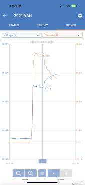
I designed our van system to directly charge relying upon a fairly high SOC about 75% or 80%. Our AGMs can take 83 amps & the manufacture’s ideal charge current is 50 amps. I have a 80 amp “slow to blow” fuse feeding the system & a 100 amp ( spare backup ) & #1 AWG. My point is the design use was to control the charge rate by internal resistance of the 250Ah AGMs & if it got outta hand, the fuse would blow, or we would run the Honda to top up so the non-DC2DC could operate below the 80 amps. For almost 2 years the theory of design worked well. Then with our new more hiking / less driving trip & the effect if accumulative non 100% SOC top offs, I saw the largest amperage spike we have ever encountered ,,, I would typically see 60 or 70 amps ,,, but not 88 amps. These spikes settle down quickly & the charge rate is usually around 50 amps after a few minutes.

IMG_4185.png

So, I sat in the van with my Wife & we agreed the thing to do was to “Limit the Charge” & then be able to use 80% of the battery capacity ,,, not 25% of the battery.


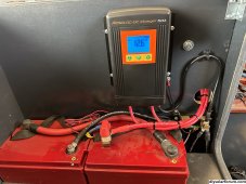
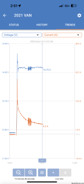
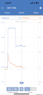
So just today I got my new Kisae 1250 wired up & operational in my Promaster Van. The unit can be user programmed 3 stages & all chemistries. Now I get the “right voltages” for Bulk / Absorption / Float & I have limited the current to 50 amps.

I have no solar, but the unit is also a solar charger ,,, if desired;


IMG_4762.jpeg


Here is a few screenshots of it @ various stages today;

IMG_4779.png


IMG_4785.png


So “Can“ You Do It Without a DC2DC ,,, Yup

and ,,, YMMV


Pros & Cons
 
Last edited:
...
@ 45' length (one way), 2/0 has a 1.89V drop @ 270A thus, the alternator will see 14.4V when the LFP battery is at 12.51V, which is nearly empty, so it will start tapering its output to less than 270A once the battery hits 12.51V. This assumes all connections are perfect.
All correct except that the alternator has a mechanical limit as to the max power it can generate. It is not capable of producing more than 190A at 12.0v so that limits the max current to 158A at 14.4v which is well withing the ampacity of the 2/0 wire. Then we need to add to that limit that this power is only at the rated rpms which is typically spinning faster than what the engine will run at highway speeds. I do not think I could ever see much more than 125A under any circumstances and that would be for a very short time because the battery will not stay below 13v for more than a few minutes.
 
Hmmm ? ,,, No DC2DC ,,, IMO there are “Pros & Cons” & YMMV as do the many variables & quality in DIY projects.

The Following Story is relevant to this thread but involved AGMs not Lithium;

About a week ago we arrived home from a 2 week Van Trip. During our van trip which had no DC2DC & is pretty much 100% charged by alternator, our “Van Use” changed ,,, more Mountain Hiking “Shasta & Lassen” & not as much driving each day. Further, our Honda 2200 Generator was taken off our equipment list as we never use it. Also, we do not have solar.

I designed our van system to directly charge relying upon a fairly high SOC about 75% or 80%. Our AGMs can take 83 amps & the manufacture’s ideal charge current is 50 amps. I have a 80 amp “slow to blow” fuse feeding the system & a 100 amp backup & #1 AWG. My point is the design use was to control the charge rate by internal resistance of the 250Ah AGMs & if it got outta hand, the fuse would blow, or we would run the Honda to top up so the non-DC2DC could operate below the 80 amps. For almost 2 years the theory of design worked well. Then with our new more hiking / less driving trip & the effect if accumulative non 100% SOC top offs, I saw the largest amperage spike we have ever encountered ,,, I would typically see 60 or 70 amps ,,, but not 88 amps. These spikes settle down quickly & the charge rate is usually around 50 amps after a few minutes.
...
So, I sat in the van with my Wife & we agreed the thing to do was to “Limit the Charge” & then be able to use 80% of the battery capacity ,,, not 25% of the battery.
...

So just today I got my new Kisae 1250 wired up & operational in my Promaster Van. The unit can be user programmed 3 stages & all chemistries. Now I get the “right voltages” fir Bulk / Absorption / Float & I have limited the current to 50 amps.

I have no solar, but the unit is also a solar charger ,,, if desired;
...

So “Can“ You Do It Without a DC2DC ,,, Yup

and ,,, YMMV


Pros & Cons
Yep.
All of this is in full agreement with my last comment in post #35. My analysis and system design is based on my coach and its charging and battery system and YMMV [your milage may vary]

I suspect that you do not have a 90' round trip from alternator to battery. You also might not have a 190A @ 12v alternator. I checked out my system before installing the LFP and found that it limited itself to 60A with FLA. I also knew that this would go a bit higher with LFP but not by much. I could see that the alternator was limiting the output because I had full 14.4v at the start batteries and was only getting 60A to the house batteries. I also do not need to worry about pumping too much current into my LFP batteries because they each can be charged at 200A for a total charge capacity of 400A. With my system, if I have low batteries and a short trip from one boondock to another, I fire up the generator for the drive so that I get the 60A-70A form the alternator plus the 108A from the Magnum. It takes a while to recharge a 920Ah pack that is down on its SOC. I would really like to find another 100A 12v charger to add on.
On my system, the biggest DC2DC would amount to a "why bother" charge.

I didn’t really read in-depth, but yes my van is 15’ #1AWG red ,,, 2’ to 3’ of #1 black to chassis return path. Can’t remember the voltage drop, but it was minor ,,, 220 amp alternator. Still the typical non-DC2DC voltage was around 14.2v & it wants 14.7v

We do not use a lot of electrical energy & we are self sufficient for about 2 weeks then we need fresh water (we carry 44 gals). We basically run on gasoline & propane ,,, Well & Coffee ?.

When I 1st got into the DIY van build hobby, the electrical came down to one big question really, “How are You going to Charge Your Batteries??”
 
This is important to remember, engine RPM does not equal alternator RPM in most cases. pulley ratio adjusts the speed. but to @Checkthisout point 2000rpm engine at 3:1 ratio is 6000 RPM fan on the alternator. Most alternators have a max output amperage well below the engines max RPM so the higher the RPM the better cooling without additional loads on the alternator. Idle 700 RPM might only be 50% of alternator output but 1300 RPM might be 100% and 2000 RPM is still 100%.

Right. The engine doesn't idle at 1000 RPM, I was merely demonstrating a concept.

The faster the alternator spins for a given output, the better because cooling will be better for the given output.

Can maybe put an RPM triggered relay that prevents auxiliary battery charging below 1500 RPM or something like that.
 
I didn’t really read in-depth, but yes my van is 15’ #1AWG red ,,, 2’ to 3’ of #1 black to chassis return path. Can’t remember the voltage drop, but it was minor ,,, 220 amp alternator. Still the typical non-DC2DC voltage was around 14.2v & it wants 14.7v

We do not use a lot of electrical energy & we are self sufficient for about 2 weeks then we need fresh water (we carry 44 gals). We basically run on gasoline & propane ,,, Well & Coffee ?.

When I 1st got into the DIY van build hobby, the electrical came down to one big question really, “How are You going to Charge Your Batteries??”
If your alternator output on the dash is not getting to the same voltage when charging your house batteries as it does when they are full, then you are taking too much to the house and it will cause your alternator to to overheat. In that case, a DC2DC or a LiBIM225 is a good idea.
I get 14.4v max and that is from idle upwards. Because the big diesel is a low revving engine, its alternator can handle a high ratio pulley, so they typically work much better at idle than does the alternator on a gas engine at idle.

I will freely admit that I am an energy hog. My 40' motorhome is all electric, so I have no propane for cooking or heating water. It is all done with electricly and a diesel hydronic heater that is run on 12v. My wife and I also work out of our coach, so we have three large high-powered computers, 5-monitors and two printers also that run most of the time. I go through about 400Ah per day so fast charging is very important.
 
Last edited:
If your alternator output on the dash is not getting to the same voltage when charging your house batteries as it does when they are full, then you are taking too much to the house and it will cause your alternator to to overheat. In that case, a DC2DC or a LiBIM225 is a good idea.
I get 14.4v max and that is from idle upwards. Because the big diesel is a low revving engine, its alternator can handle a high ratio pulley, so they typically work much better at idle than does the alternator on a gas engine at idle.

I will freely admit that I am an energy hog. My 40' motorhome is all electric, so I have no propane for cooking or heating water. It is all done with electricly and a diesel hydronic heater that is run on 12v. My wife and I also work out of our coach, so we have three large high-powered computers, 5-monitors and two printers also that run most of the time. I go through about 400Ah per day so fast charging is very important.

Yup

I don’t have an alternator problem, I put in a DC2DC to limit the current to not fry the AGM batteries.

”Energy Hog” ?? Well “Battery Energy” maybe. At our house we have grid electricity & natural gas. The natural gas can be used to; Cook, Hot Water, Fireplace, Furnace, Clothes Dryer, BBQ. We also have an electric heat pump for heat & AC.

Van ,,, Well we carry propane. Just a different energy that battery electricity ,,, still energy. We use propane to cook & heat the van. 1 - 20lb regular bbq size propane tank holds as much energy as 116 - 100Ah 12vdc lithium batteries ,,, So if you are an energy hog ,,, I am an energy hoarder. ?
 
Sorry but these questions cannot be answered in a simple way, so this is going to get a bit technical and have some math [shudder]. :geek:

Q1 Yes, start battery bank is two Group 31 start batteries.

Q2 You have the cause and effect backwards.
  • The battery does not "pull current". It is a sponge that soaks up current that is pushed from somewhere else.
  • Also, the wire does not limit the current. 2/0 wire as an ampacity of over 300A so the 70A is no problem at all. The copper wire inside the insulation is 5/8" diameter and has 133,000 strands of pure copper wire.
  • The voltage drop is caused by the current that is passing through the wire.
    • Based on Ohms Law, the total resistance of my 90' of wire and a bunch of connections is 0.02 Ω. I know this because back at the engine, the alternator output voltage is 14.4v but up at the house batteries at the other end of the 40' motorhome, the voltage is only 13.0v while 70A are being pushed into the LFP batteries. Ohms law V=Ir so r = V/I. The V is the total drop in the circuit between the sourse (alternator) and the load (LFP battery). In this case 14.4v - 13.0v = 1.4v.
      Therefore r = 1.4v/70A = 0.02 Ω.
      Because of the extremely low internal resistance of LFP, the voltage at the LFP battery will always be the battery voltage and it does not change much with the addition of large amounts of current. It only changes once the battery gets full.
    • The battery wants all the current it can get so if the voltage was not regulated, it would pull the full 190A that the alternator can produce (minus what is being used by the chassis). So, if the alternator was not voltage regulated, the voltage drop in the wire would V = Ir = 190A x 0.02 Ω= 3.8v. At which point the alternator would be putting out 13.0v + 3.8v = 16.8v. It is a darn good thing that alternators have regulators to control the power output.
    • Because 16.8v is much higher than the 14.4v set voltage of the regulator, the regulator reduces the field current to the alternator so that it puts out fewer watt of power which reduces the amps sent to the battery until only 70A are getting to the battery which brings us down to 13.0v at 60A and 14.4v at the alternator.
Q3 Here we are at cause and effect again. We rely on the alternator's regulator to control the power output (W) to not allow the voltage at its terminals to go over 14.4v. If everything is fully charged and all batteries are at 14.4v and there are no other loads, the regulator will reduce the field current to the rotor to 0A and no power will be generated. Fortunately, the designers of alternators know of the dangers of overcharging. Because of this, the regulator is designed to fail open rather than closed. If the regulator fails, it will not produce any power and charging will cease. The current to the LFP is therefore controlled by the non-changing resistance of the circuit and the max voltage of the alternator. At a worst case, if the LFP was completely dead at 2.5v per cell or 10.0v the max possible voltage drop would be 14.4-10.0 = 4.4v. with 0.02 Ω of resistance in the circuit the current would be 4.4v/0.02 Ω = 220A. This is more than the max output of the alternator so the alternator would top out at 190A at a voltage of 13.8v at the alternator. Even this is not a concern because this is in the very steep part of the charge curve and because of that, the voltage of the battery will rapidly increase so that within minutes it would be up around 13.0v and we are down to our happy 70A.

Q4 LFP's do not pull power. They absorb what is pushed to them by all of the power generating sources. In the case of the alternator, it can only push a max current of 190A and a max voltage of 14.4v at any current less than its max power output.

I am sure that the power wise out there have noticed the linguistic error I have made. I used the US standard nomenclature of referring to alternator output in terms of amps, but this is not electrically correct. The output is 190A @ 12v. An alternator is a power generator and power is measured in Watts. Therefore, the output of my alternator is P = Iv or 190A x 12.0v = 2280w. This means that the max current it can produce at 14.4v is 2280/14.4 = 158A so that is what would be sent to the battery not the 190A above. This is why people often think that their alternator is not working properly when it does not produce as many amps as it says on the box. Drop the voltage down to 12.0v and run it cold and it should be close.
This all makes total sense but I feel your results are skewed a lot because of the lead acid batteries being in the system.

The biggest thing I'm confused about is how is the amperage being limited to 70a. The regulator is adjusting the field to keep the output voltage at 14.4V AT the alternator which is 13V at the batteries. What is stopping it from pulling 190A? I've never really understood this part of electricity.

Its super important to me as I've been having a ton of issues trying to get my alternator to charge my lfp batteries. There's a couple posts on here about it. I have a 50DN 24v 270a alternator dedicated to my house (separate alt for my chassis) it was setup with a 12V regulator and set to 14v controlled by the field. I replaced this external regulator with a Wakespeed WS500 and was able to pump out close to 3000w through the 2/0 gauge cable 40' from the DP engine to my LFP bank. Problem is the voltage would spike and the wakespeed would shutdown. I adjusted the wakespeed settings to program it from a 12V to a 13V system to help bypass the voltage issue and the spike was higher which fried a ton of my 12V electronics including my battery BMS's. (didn't know it spiked before until this).

My current plan is to connect this huge 270A alternator to my chassis 70A alternator to my 24V chassis battery system (4x12V in series/parallel with a Vanner equalizer) then run multiple DC to DC converters. I'm putting 4x 24/48v 8.5a converters then 2x 24/12v 70a converters as I have both a 12V and 48V LFP system. I have this running with just the chassis and 1 24/48v converter and it works well but pulls 100% of the amperage at around 54V until the battery is 100% full. The Victron converters have voltage adjustment screws. Ideally I want them to charge only 80-90% then use solar to top off as to not waste solar. The 12V LFPs are a couple feet from the converters and the 48V are 25ft or so with I believe 0 gauge wire
 
The regulator is adjusting the field to keep the output voltage at 14.4V AT the alternator which is 13V at the batteries. What is stopping it from pulling 190A? I've never really understood this part of electricity.
The combined resistance of the wiring in the circuit, and the internal resistance of the battery bank. The voltage differential divided by that resistance gives a certain current, which is just Ohm's Law.

Problem is the voltage would spike and the wakespeed would shutdown. I adjusted the wakespeed settings to program it from a 12V to a 13V system to help bypass the voltage issue and the spike was higher which fried a ton of my 12V electronics including my battery BMS's. (didn't know it spiked before until this).
Were you monitoring the output terminal voltage of the alternator? Voltage drop is proportional to current, which means that an output voltage which is 'safe' at a high current because the battery receiving it is 'protected' by the voltage drop BASED on that current, becomes an unacceptably high voltage when the current naturally tapers (as batteries get close to full their internal resistance and terminal voltage both increase which reduces the voltage differential and increases the circuit resistance, resulting in less current), so the battery ends up 'seeing' that higher output terminal voltage. If this is enough to cause a BMS to disconnect the battery from the circuit, the voltage in the circuit will spike when that happens. You can think of this as being like 'water hammer' in a pipe if you're familiar with that.
 
The combined resistance of the wiring in the circuit, and the internal resistance of the battery bank. The voltage differential divided by that resistance gives a certain current, which is just Ohm's Law.


Were you monitoring the output terminal voltage of the alternator? Voltage drop is proportional to current, which means that an output voltage which is 'safe' at a high current because the battery receiving it is 'protected' by the voltage drop BASED on that current, becomes an unacceptably high voltage when the current naturally tapers (as batteries get close to full their internal resistance and terminal voltage both increase which reduces the voltage differential and increases the circuit resistance, resulting in less current), so the battery ends up 'seeing' that higher output terminal voltage. If this is enough to cause a BMS to disconnect the battery from the circuit, the voltage in the circuit will spike when that happens. You can think of this as being like 'water hammer' in a pipe if you're familiar with that.

Thanks for the info, still learning about this side. This makes a ton more sense now.

I was monitoring at the shunt and the wakespeed would get an error and the shunt (whole 12v) system would shut down from a main relay disconnect switch. The victron shunt wouldn't log because it lost power. After setting it on its own battery and testing thoroughly I found out it was spiking. Then found out its actually a 24V alternator because of course the one spot the plate rusted was the voltage. I'm not sure where the wakespeed reports its voltage as it has wiring to the shunt and the alternator, which I'm sure it uses to determine losses and maximizes flow.

My main concern is running 2 alts connected to my chassis batteries and all these DC to DC connectors and one alt being 4x stronger than the other. I might just disconnect the small alt's field wire more i think about it. Then keep it as a backup and a simple switch to turn it on.
 

Attachments

  • 1697732421249.png
    1697732421249.png
    280.1 KB · Views: 4
I suppose my next question would be if you are using the Wakespeed Configuration Tool on a pc/tablet/etc or just using the dip switches? I don't have time to dig through the manual right now but it's quite possible that the wakespeed is doing something you don't realize that could be prevented by some adjustment in the settings. From the brief overview i just read it definitely seems like it SHOULD have the configurability to set limits which would prevent these voltage spikes. But you'd need access to the software OR some other kind of logging or real time monitoring to move forward, i think.
 
I suppose my next question would be if you are using the Wakespeed Configuration Tool on a pc/tablet/etc or just using the dip switches? I don't have time to dig through the manual right now but it's quite possible that the wakespeed is doing something you don't realize that could be prevented by some adjustment in the settings. From the brief overview i just read it definitely seems like it SHOULD have the configurability to set limits which would prevent these voltage spikes. But you'd need access to the software OR some other kind of logging or real time monitoring to move forward, i think.
I have the configuration tool but not the pro one. There actually isn't any limits that I could find in any documentation but the coach came with a 12V master cutoff relay and it was tripping so when it came back on I'd get the wakespeed error and it was off. Wasn't until I used a separate battery for the victron I saw the voltage was spiking. I then used the voltage configuration tool and adjusted it from the auto voltage mode to 1.1 where 1=12v 2=24v so 1.1 was a custom 14v or so but still kept the lithium charging profiles the same. It then spiked to 20V and fried a bunch of stuff.

I think the issue was I assumed it was 12V because the 12V regulator and 12V dead 8D LA house batteries when I bought it. But because its 24V the WS500 was using the field to keep the voltage down but would skip a beat and it cranked up for a split second causing things to fry. It would typically run for 10-20 minutes fine until the error and multiple times I'd just turn the coach off then back on if in traffic.

Now I figure since I have the Wakespeed and all these DC to DC converters I'll be able to use the 24V and get twice the power from the alternator plus convert it to 48V which is my main bank. I have another thread about this on here that I'll update later this week as I just got all the equipment for my build. Don't want to hijack this thread with my issues.
 
This all makes total sense but I feel your results are skewed a lot because of the lead acid batteries being in the system.

The biggest thing I'm confused about is how is the amperage being limited to 70a. The regulator is adjusting the field to keep the output voltage at 14.4V AT the alternator which is 13V at the batteries. What is stopping it from pulling 190A? I've never really understood this part of electricity.

Its super important to me as I've been having a ton of issues trying to get my alternator to charge my lfp batteries. There's a couple posts on here about it. I have a 50DN 24v 270a alternator dedicated to my house (separate alt for my chassis) it was setup with a 12V regulator and set to 14v controlled by the field. I replaced this external regulator with a Wakespeed WS500 and was able to pump out close to 3000w through the 2/0 gauge cable 40' from the DP engine to my LFP bank. Problem is the voltage would spike and the wakespeed would shutdown. I adjusted the wakespeed settings to program it from a 12V to a 13V system to help bypass the voltage issue and the spike was higher which fried a ton of my 12V electronics including my battery BMS's. (didn't know it spiked before until this).

My current plan is to connect this huge 270A alternator to my chassis 70A alternator to my 24V chassis battery system (4x12V in series/parallel with a Vanner equalizer) then run multiple DC to DC converters. I'm putting 4x 24/48v 8.5a converters then 2x 24/12v 70a converters as I have both a 12V and 48V LFP system. I have this running with just the chassis and 1 24/48v converter and it works well but pulls 100% of the amperage at around 54V until the battery is 100% full. The Victron converters have voltage adjustment screws. Ideally I want them to charge only 80-90% then use solar to top off as to not waste solar. The 12V LFPs are a couple feet from the converters and the 48V are 25ft or so with I believe 0 gauge wire
I have some statements and questions before I can offer any opinion.

The statement is again, batteries do not pull current the generator pushes power in watts and the battery accepts that power. If you always think in those terms it will start to get easier to understand how to design your own system. One way to look at electricity is to think in terms of water flow which actually use very similar equations. Voltage is the same as pressure. Current is the same as flow in gallons per minute and resistance is still resistance to flow. In order to have any flow, you must have a higher potential at one end.

As for the FLA skewing the results, that is not correct. The LFA is getting the same 14.4v it has always gotten. If it is full it takes in very few amps from the alternator and if it is less then full it takes as many as it can get. Being a start battery, it usually is mostly full and only needs to recharge what is used to start.

Your system is completely different than mine with a seperate alternator for each battery bank, so I need to know more about how you have it set up. For what its worth, I would love to have your system because that is absolutely the best way to go, and you have the ability charge your batteries any way you want. It is not a Cadilac system it is a Roles Royse system.
Q1 Where does your Wakespeed get its "sense voltage" from? That would be the black/yellow and red/yellow wires on the battery bank cable.
Q2 Was any advanced programing done on the WS500 or is it just on the defaults?
Q3 Why would you want to take an RR system and make it preform like a Model-T?

From what you describe, it sounds like there are some install and programing issues that are confusing your system.
FWIW, if you decide to go to DC2DC chargers can I buy your WS500 from you because it would not be doing much of anything at that point.
 
Thanks for the info, still learning about this side. This makes a ton more sense now.

I was monitoring at the shunt and the wakespeed would get an error and the shunt (whole 12v) system would shut down from a main relay disconnect switch. The victron shunt wouldn't log because it lost power. After setting it on its own battery and testing thoroughly I found out it was spiking. Then found out its actually a 24V alternator because of course the one spot the plate rusted was the voltage. I'm not sure where the wakespeed reports its voltage as it has wiring to the shunt and the alternator, which I'm sure it uses to determine losses and maximizes flow.

My main concern is running 2 alts connected to my chassis batteries and all these DC to DC connectors and one alt being 4x stronger than the other. I might just disconnect the small alt's field wire more i think about it. Then keep it as a backup and a simple switch to turn it on.
If your small alternator is the stock alternator on your chassis, it will not have a field wire. Only an externally regulated alternator has a field wire. most stock alternators are internally regulated and do not have a field wire. They may have an excite wire but all that does it tell the alternator to turn on but the field is controlled internally by its built-in regulator.
 
Thanks for the info, still learning about this side. This makes a ton more sense now.

I was monitoring at the shunt and the wakespeed would get an error and the shunt (whole 12v) system would shut down from a main relay disconnect switch. The victron shunt wouldn't log because it lost power. After setting it on its own battery and testing thoroughly I found out it was spiking. Then found out its actually a 24V alternator because of course the one spot the plate rusted was the voltage. I'm not sure where the wakespeed reports its voltage as it has wiring to the shunt and the alternator, which I'm sure it uses to determine losses and maximizes flow.

My main concern is running 2 alts connected to my chassis batteries and all these DC to DC connectors and one alt being 4x stronger than the other. I might just disconnect the small alt's field wire more i think about it. Then keep it as a backup and a simple switch to turn it on.
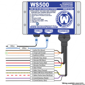
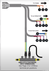
Where is the shunt. It is typically mounted on the negative wire and can be anywhere from at the battery to the other end of the main negative wire. The WS500 gest connected to the shunt with a [12] gray and [13] purple wire but these are not the battery sense wires. The sense wires are [10] black/yellow and [11] red/yellow and should be connected preferable to the battery terminal studs.

The WS500 is a fantastic tool but very complex and if you do not fully understand everything that is going on i would suggest having it checked out by a competent professional WS500 installer. Not just any RV electrician can properly set up a WS500.

ws500 wiring.png

This is a nearly 4-hour deep dive into the SW500.

 
I have some statements and questions before I can offer any opinion.

The statement is again, batteries do not pull current the generator pushes power in watts and the battery accepts that power. If you always think in those terms it will start to get easier to understand how to design your own system. One way to look at electricity is to think in terms of water flow which actually use very similar equations. Voltage is the same as pressure. Current is the same as flow in gallons per minute and resistance is still resistance to flow. In order to have any flow, you must have a higher potential at one end.

As for the FLA skewing the results, that is not correct. The LFA is getting the same 14.4v it has always gotten. If it is full it takes in very few amps from the alternator and if it is less then full it takes as many as it can get. Being a start battery, it usually is mostly full and only needs to recharge what is used to start.

Your system is completely different than mine with a seperate alternator for each battery bank, so I need to know more about how you have it set up. For what its worth, I would love to have your system because that is absolutely the best way to go, and you have the ability charge your batteries any way you want. It is not a Cadilac system it is a Roles Royse system.
Q1 Where does your Wakespeed get its "sense voltage" from? That would be the black/yellow and red/yellow wires on the battery bank cable.
Q2 Was any advanced programing done on the WS500 or is it just on the defaults?
Q3 Why would you want to take an RR system and make it preform like a Model-T?

From what you describe, it sounds like there are some install and programing issues that are confusing your system.
FWIW, if you decide to go to DC2DC chargers can I buy your WS500 from you because it would not be doing much of anything at that point.
Totally makes more sense now.

1. I ran a couple pairs of cables all the way to the front so the sense voltage was at the lynx distributor right by the batteries 40ft. Same with the shunt wires.

2. I changed some settings for the profile and such to match how I wanted to charge. Also set a limit of 250a then down to 200a. Went through every setting and all is right, only thing was I never got the pulley size right so the rpm was off but didn't use that. Just used a 1 min delay before turning on

3. I don't. I love the wakespeed and it integrates with Victron so I could watch how much it's working and my alt temps. But my alt is 24v and batteries are 12v and 48v separate systems. I should swap my 12v quattro for a 24v one and just use a 24/12 Orion for 12v loads since it's just lights and electronics... or just use 120v to 12v as I also have this setup as a backup. My battery bms's are fried I think so can get a 24v bms.

I did buy a 24v regulator for my 50dn alt so I could get rid of the wakespeed.

I think I could use the wakespeed as a 12v and just connect my 12v generator battery so it'll help absorb any spikes... as it's also a separate system. But 12v would be half the watts through the 2/0.

Another option I've been thinking is a 48v 100a balmar and have a 3rd alt as I have a bracket for it and room. But it's 3k and I don't need that much power. 2kw for my main 48v system and 2kw for the aux 12v system is plenty.
 
Where is the shunt. It is typically mounted on the negative wire and can be anywhere from at the battery to the other end of the main negative wire. The WS500 gest connected to the shunt with a [12] gray and [13] purple wire but these are not the battery sense wires. The sense wires are [10] black/yellow and [11] red/yellow and should be connected preferable to the battery terminal studs.

The WS500 is a fantastic tool but very complex and if you do not fully understand everything that is going on i would suggest having it checked out by a competent professional WS500 installer. Not just any RV electrician can properly set up a WS500.

View attachment 173075

This is a nearly 4-hour deep dive into the SW500.

I ran 2 pairs of wires 40ft (plus cat6 for CAN) to the LFP bank. Shunt was wired correctly on the shunt and the voltage + and - were on my LYNX distributor with + on the same lug as the 2/0 alt wire. I confirmed the voltage in the ws was reading the same as my battery voltage.
 
Back
Top