diy solar

diy solar

Design feedback

Padlynn

New Member
Joined
Oct 4, 2022
Messages
1
Hi all,
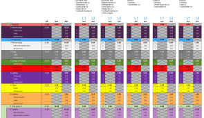
Some solar design for open criticism. It's been really informative reading the many post here. Thanks for the information. My design seems a little too simple for nothing to be wrong.

Thank you, Steve
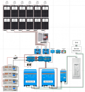
  • Plan to upgrade from a 150A main panel to a 200A panel first, to be able to accommodate an EV charger at some point in the future. Also, more spaces in the panel as we may add on next year (Upgrading to a smart panel too, so I can monitor and control at a CB level)
  • 6x2 solar combiner with 15A per string protection / Solar cutoffs in the PV combiner box / South facing solar
  • Solar controllers would be 2x Victron MPPT 150/70 TR-VE.Can
  • Victron 48VDC/12VDC for the Cerbo GX and other 12VDC needs
  • Lynx distribution and Cerbo GX for system management
  • I want to prioritize solar/battery, but Grid is backup / No desire to export to grid (i.e. zero-export)
  • Battery bank to accommodate dips in generation throughout the day and for backup (I can turn things off in the event of an extended outage to extend)
  • 2 Victron Quattro 48V/5kW/120VAC inverters in split phase (looking for the 100A pass through that these are rated for to go with a 200A panel)
  • 100A Victron autotransformer (balancing the legs) / Due to the loads on my panel, I can have up to a 25A differential between the legs
  • No critical loads panel, I want to push everything through one panel
  • Would add a 200A breaker between the grid and the inverter inputs (Not shown, but where the service disconnect would be)
  • Expandability options: More batteries, more solar if needed (thus the extra feed ins on the Lynx Power in)
  • Communication cables not shown
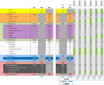
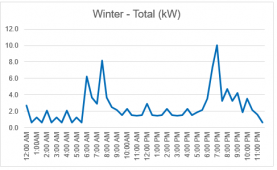
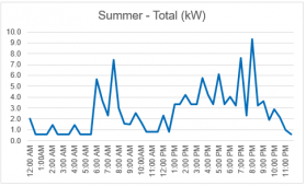
  • Also, my electrical consumption model of the house is below.
Questions
  • Would I need a transfer switch for cutoff in the event of grid disruption (anti-islanding)? Not positive if the Quattros do this or if I need a separate device.
  • Does the Quattro actually blend grid and solar / battery power? / In other words, does it just use the solar/battery until below a certain SOC and then switch over the whole source to grid by going into bypass mode? I have not been able to get a good idea of this, based on what I've read. Not sure how much of a difference this makes, but is seems like blending would reduce the number of cycles on the batteries.
  • Additional fusing / breakers? I might bump the 100A fuses in the Lynx Distributor to 125A and bump the breakers on the MPPT outputs to 80A.
Solar design.PNGModel.PNGSpreadsheet.PNGWinter day.PNGSummer day.PNG
 
I am by no means an expert…

The Cerbo power input is from something like 10v to 70v - so you don’t need a 48v12v converter for it. It can plug into the 48v.

You have two power switches between the power in and the shunt. I have not seen switched negative wires - if you do that, make sure the negative is the last off and first on.
I would eliminate these switches unless you have a vital need for them. I see them as redundant. All your batteries have a switch, you have a breaker(switch) on your mppt’s.

Instead of getting a distributor get another power in - some nuts and bolts and then you can have a power in that has fuses. The only thing that is missed is the led lights that shows if a fuse is blown. (And it saves money). There are several YouTube videos on how to do that.

Your PV combiner box - can’t tell - does it have fuses for each Pv string. 3p strings need fuses.

Fuse on the batteries- use a class T fuse and fuse holder. The picture shows a different fuse.

You MUST move the PV wires to the “distributor” side of the shunt. As it is now, the shunt will not recognize any of the power being generated- the Cerbo will say batteries are at 0% when they could be full.

You will then have four slots in the power in and four SOK batteries maybe connect each battery to its own slot on the power in. At the least, the positive wire to the power in needs to come from the top of the stack and the negative wire from the bottom of the stack. (Connecting each battery to the power in would be better). Be sure and use exactly the same length of cables for all four batteries.

I can’t help on the using solar/batteries instead of grid. That is all done with “Assistants”. I think you will be using the ESS assistant - but I don’t really know.

Contact your Victron dealer and make sure they know that area well so they can help you. Also show your plans to your Victron dealer before starting.

I think you have an error in logic on upgrading the panels to 200a. The inverters can only handle 100a of pass through current. With two inverters that’s 100a of black wire and 100a of red wire - which is 100amps of 240v service.

Make sure your household usage can run under the 4000watts that each can produce. Also as the inverters get hot their output drops - down to 3000w if they get to 150 degrees F. (Can you household handle that level?).

You may want to install an inverter bypass, so your house does not lose power if you take the inverters down for service. This needs done properly, with cut outs.

Good Luck - looks like a great project!
 
One other thing, if you are putting six 360w panels on a solar charge controller - that’s only 2160w the mppt 150/70 can handle 4000 watts.

If just putting 6 panels use a 150/45. If putting 12 panels on a single 150/70 that’s 4320w - which will slightly overpanel the 150/70 - that’s a great spot! (2s6p)

You could also look at the mppt 250/70. And arrange the panels as 4s3p.
 
check your cerbox serial number you probably need to add the 100uF/100v capacitor on the power connector if connected to 48v directly.
 
Back
Top