diy solar

diy solar

Did some tests with shade

MarkSolar

Solar Enthusiast
Joined
Mar 3, 2021
Messages
384
Location
Chicago far metro
I have been curious about the effects of shade on my array. I have 24 panels wired in 3 strings of 8, 10kW total, they all get combined and go into one MPPT on a Fronius inverter. On a cloudless day with sun directly overhead I did 2 tests. I used a large umbrella that casts shade on ~1/2 of one panel. I used a heavy black rug to completely block one panel. Here's the loss in total array power output for the tests:
Theoretical power loss removing one panel: 4.2%
Actual power loss covering one panel with rug: 5%
Power loss with umbrella shading 1/2 of one panel: 8%

This surprised me, I've read so many accounts of dramatic reductions from partial shading that I assumed I would see very large reductions in output. Is it possible a single tracker on a string inverter is more efficient than expected, or am I not understanding something.
 
I shaded a single series Of three panels, 100 watts each. Shading two cells on a 30+ cell panel I got a 25% - 33% reduction. When I shaded half a panel out of three panels, I got a 75% reduction.

Big difference between our two tests.


I’m interested in the math you used to get your 4.3% loss.
 
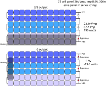
The effects of shading is very much dependent on where the shading is relative the string arrangement to the bypass diodes. A smaller area can be more damaging then a larger area if it encompasses multiple bypass groups.

Panel long row pairs (down and back) go into one bypass diode in the junction box. Six row panel will have 3 bypass diodes. A shade down one row will just knock out that row pair leaving 4 rows producing. In contrast, a shade across the short width of panel effects all row pairs knocking out just about all production from the panel.

When a single cell is shaded it can be reverse biased. This typically knocks out all cells in the two rows the shaded cell is a member of. A bird dropping will reduce the current from one cell. That acts like a cell producing less current and will reduce current in all series cells by a similar amount.

With three series strings in parallel thing get more complicated. The partially shaded string will drag down the MPPT voltage point the controller decides is best and this effects output of the two totally unshaded panels.

Many panels have marginal quality bypass diodes. They can get very hot when called upon to bypass a row pair. They often go bad from the excessive heat. Any panel that puts multiple diodes in parallel to get higher bypass current is a poor design. They would have to be matched diodes and assured they all stay at same temperature or one diode will take most of the current causing its destruction, followed by paralleled diodes going bad as the cascade meltdown progresses.

PV shading.png
 
Last edited:
The effects of shading is very much dependent on where the shading is relative the string arrangement to the bypass diodes. A smaller area can be more damaging then a larger area if it encompasses multiple bypass groups.

Panel long row pairs (down and back) go into one bypass diode in the junction box. Six row panel will have 3 bypass diodes. A shade down one row will just knock out that row pair leaving 4 rows producing. In contrast, a shade across the short width of panel effects all row pairs knocking out just about all production from the panel.

When a single cell is shaded it can be reverse biased. This typically knocks out all cells in the two rows the shaded cell is a member of. A bird dropping will reduce the current from one cell. That acts like a cell producing less current and will reduce current in all series cells by a similar amount.

With three series strings in parallel thing get more complicated. The partially shaded string will drag down the MPPT voltage point the controller decides is best and this effects output of the two totally unshaded panels.

Many panels have marginal quality bypass diodes. They can get very hot when called upon to bypass a row pair. They often go bad from the excessive heat. Any panel that puts multiple diodes in parallel to get higher bypass current is a poor design. They would have to be matched diodes and assured they all stay at same temperature or one diode will take most of the current causing its destruction, followed by paralleled diodes going bad as the cascade meltdown progresses.

View attachment 65003
OK, thanks for the explanation. It is hard to believe I walked out there with an umbrella and randomly picked a spot that resulted in such a small effect. Next time we have a clear day I'll try the experiment again, choosing different shade combinations that cross rows and columns. I also wasn't sure how fast trackers react to shade. The reduction in performance when I opened the umbrella showed up almost immediately. I had assumed the tracker would be able to somewhat mitigate that effect so I waited about 10 minutes for each test, but never saw any change until I removed the umbrella, then the output went up again almost immediately.
 
Removing one panel out of 24 would reduce the output by 1/24 = 4.2%
I assumed covering one panel completely would result in a value close to removing one panel.
That did not work in my case, Removing one panel (1/3rd) dropped output by 2/3rds to 3/4ths.

There probably is some math, but not sure what it is.
EDIT: After a it of thought, What @RCinFLA Posted matches the voltage loss I saw. If a panel loses 1/3 its power, it sucks the 1/3 for alt the other panels etc.
 
If you don't have enough total series panel voltage overhead above battery voltage to afford to lose a row pair or two the controller will shut down or maybe go into PWM mode if just barely above battery voltage.

A sun heated panel will have about 0.45-0.5v per cell at Vmp. A shockly bypass diode at 6-8 amps will have 0.5-0.7v diode drop depending on its max current rating. 0.6v diode drop with 8 amps is almost 5 watts of heating. A small pellet diode doesn't stand a chance of surviving the heat.

When a cell is shaded it can be given a very high reverse bias voltage by unshaded cells. The bypass diode limits the maximum reverse bias voltage to the maximum number of cells in the bypass diode group. This is to prevent a shunt defect in the shaded cell from getting too hot due to the high reverse bias.

There are some panels that put junction box in middle of long side with more bypass diodes to short column pair groups. These are good to look for especially in marine use where partial shading is always a problem.
 
Last edited:
If you don't have enough total series panel voltage overhead above battery voltage to afford to lose a row pair or two the controller will shut down or maybe go into PWM mode if just barely above battery voltage.
I’m going to spend some time looking at this this winter. I have not seen with my 12 volt system where I don’t have enough voltage for my system to charge, unless of course the sun is not up. The panels I talked about were 46 volts 3S, and when output dropped by 75%, they were still at 39 volts. Well above what the MPPT needs to charge a 12 volt battery.
 
I’m going to spend some time looking at this this winter. I have not seen with my 12 volt system where I don’t have enough voltage for my system to charge, unless of course the sun is not up. The panels I talked about were 46 volts 3S, and when output dropped by 75%, they were still at 39 volts. Well above what the MPPT needs to charge a 12 volt battery.

It may be the shaded panel still produced some current. So MPPT walked voltage down until power rose, then fell, and found Vmp/Imp for that low current. What it possibly failed to do was walk down to a lower voltage where the unshaded panels put out full current and activated bypass diode of the shaded panel.

Try covering the panel with something completely opaque.
If that results in higher power than light shade, I would blame the MPPT algorithm.
 
The effects of shading is very much dependent on where the shading is relative the string arrangement to the bypass diodes. A smaller area can be more damaging then a larger area if it encompasses multiple bypass groups.

Panel long row pairs (down and back) go into one bypass diode in the junction box. Six row panel will have 3 bypass diodes. A shade down one row will just knock out that row pair leaving 4 rows producing. In contrast, a shade across the short width of panel effects all row pairs knocking out just about all production from the panel.

When a single cell is shaded it can be reverse biased. This typically knocks out all cells in the two rows the shaded cell is a member of. A bird dropping will reduce the current from one cell. That acts like a cell producing less current and will reduce current in all series cells by a similar amount.

With three series strings in parallel thing get more complicated. The partially shaded string will drag down the MPPT voltage point the controller decides is best and this effects output of the two totally unshaded panels.

Many panels have marginal quality bypass diodes. They can get very hot when called upon to bypass a row pair. They often go bad from the excessive heat. Any panel that puts multiple diodes in parallel to get higher bypass current is a poor design. They would have to be matched diodes and assured they all stay at same temperature or one diode will take most of the current causing its destruction, followed by paralleled diodes going bad as the cascade meltdown progresses.

View attachment 65003
I like that the pictures that you post, very informative! Can you please provide the link? Thanks!
 
The impact of shading depends a lot on the type of panels and how the bypass diodes are set up. Half cut panel tend also to have good shade tolerance. Also the global MPPT algorithm in the Fronius is pretty darn good at helping to overcome intermittent shading issues.

Have a watch of this video where a solar PV company here in Australia has done some control tests of two systems side by side, a Fronius string system and an Enphase micro inverter system. It goes against what many have been led to believe about how shade affects string inverter systems.

It's 17-min long video but I reckon it's worth seeing it through.

 
There are some panels that put junction box in middle of long side with more bypass diodes to short column pair groups. These are good to look for especially in marine use where partial shading is always a problem.
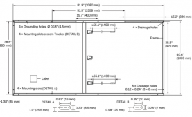
That's interesting, my panels have two junction boxes, each located in the middle of a long side:

1631881055843.png
 
The impact of shading depends a lot on the type of panels and how the bypass diodes are set up. Half cut panel tend also to have good shade tolerance. Also the global MPPT algorithm in the Fronius is pretty darn good at helping to overcome intermittent shading issues.

Have a watch of this video where a solar PV company here in Australia has done some control tests of two systems side by side, a Fronius string system and an Enphase micro inverter system. It goes against what many have been led to believe about how shade affects string inverter systems.

It's 17-min long video but I reckon it's worth seeing it through.

Thanks for that link. I also found two research papers from a Dutch university that looked at the same thing. I've attached both.
 

Attachments

  • Research paper string vs optimized 2015.pdf
    1 MB · Views: 8
  • Research paper string vs optimized 2021.pdf
    5.8 MB · Views: 12
That's interesting, my panels have two junction boxes, each located in the middle of a long side:
This is likely a half cell panel. It is wired like two smaller panels in parallel with each side's row pairs sharing a common bypass diode in the middle. Would be better if each side's shorter row pair had their own bypass diode making each bypass diode group a smaller area.

Half cell panels often mis-represent their cell count by calling half cells in parallel as a two cell count. This makes Vmp half what you think the stated panel cell count times 0.5v per cell should be.

Half cell are done primarily for manufacturing yield improvement. They cut cell to separate the side with more shunt resistance defects then match the shunt resistance half's for same panel grade. Since a full sized cell produces about 8.5 amps, half cells are also used to make a lower wattage panel.

The idea case would be a bypass diode on every cell but that is impractical from a manufacturing point of view.
 
Last edited:
I might be wrong here, but I always found (might be coincidence) that polycrystalline panels don't tolerate partial shading well at all, monocrystalline do.
 
I might be wrong here, but I always found (might be coincidence) that polycrystalline panels don't tolerate partial shading well at all, monocrystalline do.
Polycrystalline cells have a wide range of quality from 'toy' grade to performance approaching a monocrystalline cell.

I have found their quality can be judged by their appearance and Voc temp coefficient. The more 'chip woody' the surface, the worse the quality. Darker more uniform color is usually better quality. This seems to also match up with Voc temp coefficient. Good quality poly cells have Voc temp coefficient very close to nominal -0.34%/degC of monocystaline panels.

Poly cells typically have a slightly lower Vmp per cell compared to mono cells.

The only reason for an appearent shading performance difference is poly cells typically have lower cell shunt resistance. The lower the shunt resistance of a cell the poorer its low light performance will be.
 
Last edited:
Thanks for that link. I also found two research papers from a Dutch university that looked at the same thing. I've attached both.

Figure 13 vs. 12 of "Optimizer" paper shows enhancement by clouds. Power is occasionally clipped at 1500W during a six hour period, vs. 1400W peak with only direct sun. (Unfortunately spends more time with reduced power output rather than enhanced.)

The short bursts of higher current in that test wouldn't be enough to overheat wires, and probably not fuses, for which we oversize by 25%. But it could stress silicon components in SCC or inverter. Other cloud conditions could put 100% direct sun on panels plus enhancement from nearby clouds for an extended time (if we intentionally design a "degenerate" weather situation intended to cause overstress.) Murphy, you know.

Figure 17 shows about 2% loss in production due to panel optimizers (under conditions where they don't provide a benefit.)
I think that could be offset by increase if panel current is mismatched to begin with.

For someone who's MPPT doesn't find the lower voltage, higher wattage peak (figure 2 of "string vs optimized", optimizers could help by boosting current for a panel that has reduced output due to shading. Question would be what percentage of day's production is lost if not using optimizer. Since each panel has 2 or 3 sub-strings (with diode bypass), hope the optimizer itself has smart MPPT able to find highest peak.

KISS - better to have an MPPT with good algorithm, rather than additional electronics and double the connections. But for some situations, or when other electronics are required anyway (RSD), optimizers could be worthwhile.
 
That's interesting, my panels have two junction boxes, each located in the middle of a long side:

Here is a good video on half cell vs full cell. The video is slightly prejudicial to half cells but still pretty fair.

As you will see it depends on how smart the MPPT algorythm is on a particular controller to finding sub-peaks. Also depends on whether panels are a common series string or each panel is on a micro-inverter. Not discussed in video, finding sub-peaks takes more MPP search time so it can be a disadvantage to overall production output vs. time.

 
Good explanation in the video.

One configuration he didn't address was parallel panels or strings. With several in parallel, the lower voltage from activating bypass diode isn't an advantage, because full voltage from unshaded strings is where maximum power is achieved. If a half-cut panel is shaded such that it can deliver full voltage at half current, then the string it is in can still contribute (but entire string will be at half current and full voltage.)

There are also situations where either full or half-cut cell panels will both be OK. Multiple long strings in parallel, if a panel is partially shaded its maximum power point voltage is reduced, but not enough to cause double peaks in the array power/volts curve. The MPPT operating point shifts slightly, so close to maximum power is harvested from both shaded and unshaded strings. I observed that with 9s2p, shading one panel.

Pattern of shading needs to be considered. The large commercial arrays shown in the video will shade each other when sun is low, a shadow on the edge of each array. Looks like landscape vs. portrait orientation would be best there.

Rather than half-cut cells, SunPower P17 has 1/6th cut cells. Each column of cell slivers delivers full panel voltage from one row of cut cells. It is intended for those commercial arrays that shade each other.

 
What about safety on full cells? at which temperatures will it be a problem when the current reverses to the shaded cells causing them to overheat?
Is there any information on that?
 
Back
Top