


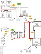
This is my second generator build. Intended to run freezer, etc. during power outages. While there are always upgrades possible, I'm requesting a sanity check for safety such as wire sizes, fuses and switches. All input is welcome.
Take care,
Terry
p.s. I've updated the drawing with a few suggestions.
Take care,
Terry
p.s. I've updated the drawing with a few suggestions.
Attachments
Last edited: