CzerwonaKrowa
New Member
- Joined
- Dec 7, 2022
- Messages
- 14
I have been lurking on these forums (especially in the up-in-smoke and LifePO4 DIY forums) and been learning a lot and thinking about a design for an unconventional battery shed that will probably stir up a lot of controversy but I have specific design requirements that I will outline and would like to brainstorm as a community to iterate on the design to make it safe, robust, and easy to maintain. Once I am satisfied with what we came up with, I will build it and continue to report on the build.
I will outline the build progressively with more details -- First, a general image showing the overall "vibe":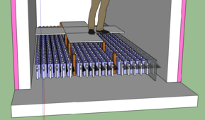
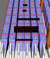
The overall idea is to build a structure almost entirely out of concrete and have the batteries be underneath a "false floor' with removable panels for servicing. Each line of batteries is a 17s arrangement of 280Ah LifePO4 cells, with the Class T fuse at the positive end (not pictured) and the BMS at the negative end (pictured). The underneath of the batteries will need some kind of 1" or so subfloor on top of the concrete to redirect moisture so that in case a leak in the structure happens the batteries won't be sitting dipped in water. The false-floor "tiles" themselves will need to be fireproof as well (tile on some kind of cement fiberboard maybe?) and the vertical 2x4's that support them will need to be changed to something fireproof as well, I just don't know what yet. For the wall-side supports I was planning on using steel L channel though I worry about the potential for that to come loose and short out that closet row of batteries. Maybe a little lip detail molded directly into the concrete pour of the structure's wall?
The balance cables for the cells will be made of various gauges of magnet wire and will run underneath the cells in some kind of channel. The image shows them running beside instead of under since that is a design decision I changed/updated/iterated on but haven't updated in the 3D model yet. This was updated to accommodate the addition of the cement fiberboard between each row of cells. The reasoning for some of these choices is that I don't like normal thin insulated wire since the insulation is just flammable fuel in case something unexpected happens and magnet wire still has insulation on it but so little that there isn't much fuel for fire. The different gauges are because in this arrangement the furthest cell is quite far from the BMS and the closest is very close so there will need to be a variety of gauges of the balance wire to keep the BMS happy with the wire resistances to the cells (already tested/experimented with the JK BMS es I have for this and indeed it's necessary). They need to run underneath the cells because I want maintenance to be dead-simple. I don't want to untangle a rats nest of balance wires that run above the cells to pull a single cell out and replace it. The balance wires will come up between sequential cells and attach with an alligator clip to the bar that links cells. A lot of people around here bash on alligator clips for balance wires and that's something I don't understand -- you want the balancing and cell monitoring system to lean towards the failure side. For example, if an alligator clip accidently gets knocked off, the BMS will see 0 volts for that cell and disconnect. It's almost like a trip-wire system in that regard. I prefer to keep disconnect/safety sensory systems on the fail-sooner side than drilling a hole in a busbar for a super-solid connection for a balance wire that should never see more than 2A of current through it.
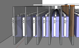
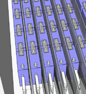
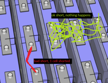
Each row has 17s LifePO4 (I prefer 17s to 16s in my experimentation because the voltage ranges for my inverters is happier with the slightly higher voltage range from 17s instead of 16s and all of my BMSes are up-to-20s anyway, and if you don't want the 17th cell you can remove it and run 16s instead). Between each row, there is a cement fiberboard (pictured at the very right there for just that 1 row but in the final build all rows will have them) and also a cement fiberboard fragment between each series cell as well (not pictured) with a small slit cut out for the cell-to-cell link to poke through and connect the cells in series to one another. This "interlinking" grid of cement fiberboard is to try to contain individual cell failures (think internal hard short) as much as possible.
The negative end of the pack and the positive end of the pack will be at complete opposite ends of the structure and I am considering using uninsulated wire to link everything to link everything together (past the Class T fuse on the + end and past the BMS on the - end) to a big 1000-2000A copper busbar on each end forming the positive and negative rails, using some kind of fire-proof but non-metallic bracket (not sure what) to mount it to the concrete walls of the structure. I want to avoid insulation since the only voltages in this building are 48V nominal (60V max) so they don't pose much shock hazard and insulation on wires is a huge fire fuel for any electrical faults.
Other thoughts are -- I want the building to have a ~4000-5000CFM explosion-proof all-metal ventilation fan that will turn on if smoke is detected (they cost about $1k) so that if a battery goes and starts venting the explosive vapors are expelled out of the before the air-fuel mixture reaches ignitable levels. The plans are to house all of the inverters and other electrical equipment outside of this structure so that a battery fire that destroys ~$40k of batteries doesn't also destroy another ~$30k of other electrical equipment.
Finally, I still haven't figured out what to use for battery heating for winter time or a general forced air ventilation option to keep air flowing into the under-the-false-floor chamber to keep the temperature consistent or whatnot and there's a lot of other details not figured out yet as well such as concerns about rodent damage and ease-of-inspection. I will answer questions and keep iterating on this for at least a few months before I begin building this. I welcome suggestions and a discussion around the design of this thing.
I will outline the build progressively with more details -- First, a general image showing the overall "vibe":

The overall idea is to build a structure almost entirely out of concrete and have the batteries be underneath a "false floor' with removable panels for servicing. Each line of batteries is a 17s arrangement of 280Ah LifePO4 cells, with the Class T fuse at the positive end (not pictured) and the BMS at the negative end (pictured). The underneath of the batteries will need some kind of 1" or so subfloor on top of the concrete to redirect moisture so that in case a leak in the structure happens the batteries won't be sitting dipped in water. The false-floor "tiles" themselves will need to be fireproof as well (tile on some kind of cement fiberboard maybe?) and the vertical 2x4's that support them will need to be changed to something fireproof as well, I just don't know what yet. For the wall-side supports I was planning on using steel L channel though I worry about the potential for that to come loose and short out that closet row of batteries. Maybe a little lip detail molded directly into the concrete pour of the structure's wall?
The balance cables for the cells will be made of various gauges of magnet wire and will run underneath the cells in some kind of channel. The image shows them running beside instead of under since that is a design decision I changed/updated/iterated on but haven't updated in the 3D model yet. This was updated to accommodate the addition of the cement fiberboard between each row of cells. The reasoning for some of these choices is that I don't like normal thin insulated wire since the insulation is just flammable fuel in case something unexpected happens and magnet wire still has insulation on it but so little that there isn't much fuel for fire. The different gauges are because in this arrangement the furthest cell is quite far from the BMS and the closest is very close so there will need to be a variety of gauges of the balance wire to keep the BMS happy with the wire resistances to the cells (already tested/experimented with the JK BMS es I have for this and indeed it's necessary). They need to run underneath the cells because I want maintenance to be dead-simple. I don't want to untangle a rats nest of balance wires that run above the cells to pull a single cell out and replace it. The balance wires will come up between sequential cells and attach with an alligator clip to the bar that links cells. A lot of people around here bash on alligator clips for balance wires and that's something I don't understand -- you want the balancing and cell monitoring system to lean towards the failure side. For example, if an alligator clip accidently gets knocked off, the BMS will see 0 volts for that cell and disconnect. It's almost like a trip-wire system in that regard. I prefer to keep disconnect/safety sensory systems on the fail-sooner side than drilling a hole in a busbar for a super-solid connection for a balance wire that should never see more than 2A of current through it.
Each row has 17s LifePO4 (I prefer 17s to 16s in my experimentation because the voltage ranges for my inverters is happier with the slightly higher voltage range from 17s instead of 16s and all of my BMSes are up-to-20s anyway, and if you don't want the 17th cell you can remove it and run 16s instead). Between each row, there is a cement fiberboard (pictured at the very right there for just that 1 row but in the final build all rows will have them) and also a cement fiberboard fragment between each series cell as well (not pictured) with a small slit cut out for the cell-to-cell link to poke through and connect the cells in series to one another. This "interlinking" grid of cement fiberboard is to try to contain individual cell failures (think internal hard short) as much as possible.
The negative end of the pack and the positive end of the pack will be at complete opposite ends of the structure and I am considering using uninsulated wire to link everything to link everything together (past the Class T fuse on the + end and past the BMS on the - end) to a big 1000-2000A copper busbar on each end forming the positive and negative rails, using some kind of fire-proof but non-metallic bracket (not sure what) to mount it to the concrete walls of the structure. I want to avoid insulation since the only voltages in this building are 48V nominal (60V max) so they don't pose much shock hazard and insulation on wires is a huge fire fuel for any electrical faults.
Other thoughts are -- I want the building to have a ~4000-5000CFM explosion-proof all-metal ventilation fan that will turn on if smoke is detected (they cost about $1k) so that if a battery goes and starts venting the explosive vapors are expelled out of the before the air-fuel mixture reaches ignitable levels. The plans are to house all of the inverters and other electrical equipment outside of this structure so that a battery fire that destroys ~$40k of batteries doesn't also destroy another ~$30k of other electrical equipment.
Finally, I still haven't figured out what to use for battery heating for winter time or a general forced air ventilation option to keep air flowing into the under-the-false-floor chamber to keep the temperature consistent or whatnot and there's a lot of other details not figured out yet as well such as concerns about rodent damage and ease-of-inspection. I will answer questions and keep iterating on this for at least a few months before I begin building this. I welcome suggestions and a discussion around the design of this thing.
Last edited:


