diy solar

diy solar

DIY Van Electical System: 24V/280A Battery + 1020W Solar

I made the updated schematic which includes the BMS and the Victron Smart Shunt (500A)

The Smart shunt will connect to the CCGX of the EasySolar along with the smaller MPPT through the VE.Direct ports. And since the reading from the Smart shunt will be the main voltage reading source which all other Victron components will use, i can set the charge upper limit to 80% and the discharge lower limit to 20%. That will prevent the BMS from even getting close to trigger a disconnect. It will be there just in case something goes bad with my settings and to ballance the cells. I think i can get by with only using 60% of the battery capacity, maybe 70% if i push the SoC to 90%.
What do you guys think?

safdfas.jpg
*ballance cables not connected in the diagram, they will be connected in real life.
 
  • Like
Reactions: Dzl
A BMS also protects against an equipment failure. Charger, stuck relay, etc. Echoing the others, running without one is foolish. Only expert operators with experience and the tools to match cells should even consider it. Given the modest cost, it makes little sense to skip this part of the build.
 
  • Like
Reactions: Dzl
I'm not skipping it, as you can see, i'm adding one. I wanted not to initially, but all the replies i got changed my mind. Thanks.
 
  • Like
Reactions: Dzl
Schematic looks good at first glance.

Remind me why you are going with a second charge controller?

As to SOC limits, I think if you cells are moderately matched, and balanced, 90-20% would be reasonable and safe, and should keep the BMS from triggering (Daly has wide bandwidth (2.5v to 3.7v I think) so 90-20 should keep you well away from those limits).

When you receive, balance, and capacity test your cells, you can get a better idea of sensible limits.
 
Remind me why you are going with a second charge controller?
I have two sets of solar pannels, 2x160W and 2x350W, both sets connected in series. The smaller SCC is for the 160W panels. The 350W ones connect to the EasySolar's MPPT. I don't think there's a efficient way to connect the pannels so that they'll all use the Easysolar instead.
When you receive, balance, and capacity test your cells, you can get a better idea of sensible limits.
Yeah, i should have them in a week or so. The BMS will take a while...
 
  • Like
Reactions: Dzl
Hi everyone, i finally finished the electrical system on the van...sort of...not 100%. This project took waaay longer than i thought, most of the time i was waiting for parts to arrive.

Since last time, i made some modifications to the initial design based on your advice, i added a 65A Battery Protect to disconnect the 12v and 24v loads when the voltage gets too low.
I capacity tested the cells a few times and top ballanced them. I pulled 8Ah more than they were rated for, wich is normal from what i've seen on Will's video's. I placed them in series and they stay ballanced at the top with no more than 0.002 deviation, and 0.03 during loads and towards the very bottom. The battery will be charged to 26.8v with float at 26.6v, and discharged to 25.6v (+250Ah/+6500Wh usable power), although the 65A Battery Protect highest low disconect point is only 24v...wich is not that bad considering that Daly's BMS low voltage cutt-off is 17.6v...ridiculous.

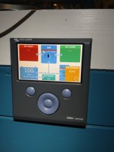
The charging is sinchronized between the two charge controllers and it's based on the information coming from the 500A SmartShunt, wich comunicates them the battery voltage, curent and temperature. Both chargers are grounded to the chasis.

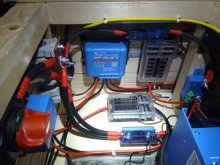
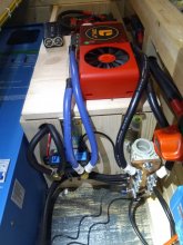
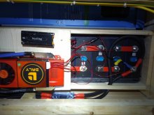
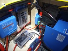
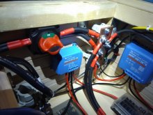
As for the cables, i have 2x35mm² thin stranded welding wire going to each buss bar with a 200A fuse. From there to the EasySolar i have 2x25mm² each way with a 150A fuse. Going to the Battery Protect there's one 16mm² with a 60A fuse. All other wires are 10mm² exept for the solar cables (4mm²) and dc loads from fuse boxes (1.5mm²). The ground wire going from the 100/20 MPPT is 10mm², and for the 150/70 MPPT is 16mm².

I have some photos i would like to show you

IMG_20201211_120323.jpgIMG_20201213_105543.jpgIMG_20201213_105643.jpgIMG_20201213_105723.jpgIMG_20201213_105742.jpgIMG_20201213_105950.jpg


I'm planning to add some fuses going into and from the dc-dc converter (it already has one 20A fuse internally) and from the Battery Protect going into the 24v fuse box. Not sure if i need one for the 100/20 MPPT as well, since it has a 25A internal fuse just like the dc-dc converter, but it also has short circuit protection on top of that. The Battery Protect also has short circuit protection. What do you guys think, where is necessary to add a fuse?


Anyway, i wanted to let you know of the changes and show you how it turned out, but mostly to thank you for your advice and for the patiance you had teaching me this things. Thank you very much!
 
  • Like
Reactions: Dzl
Hi everyone, i finally finished the electrical system on the van...sort of...not 100%. This project took waaay longer than i thought, most of the time i was waiting for parts to arrive.

Since last time, i made some modifications to the initial design based on your advice, i added a 65A Battery Protect to disconnect the 12v and 24v loads when the voltage gets too low.
I capacity tested the cells a few times and top ballanced them. I pulled 8Ah more than they were rated for, wich is normal from what i've seen on Will's video's. I placed them in series and they stay ballanced at the top with no more than 0.002 deviation, and 0.03 during loads and towards the very bottom. The battery will be charged to 26.8v with float at 26.6v, and discharged to 25.6v (+250Ah/+6500Wh usable power), although the 65A Battery Protect highest low disconect point is only 24v...wich is not that bad considering that Daly's BMS low voltage cutt-off is 17.6v...ridiculous.

The charging is sinchronized between the two charge controllers and it's based on the information coming from the 500A SmartShunt, wich comunicates them the battery voltage, curent and temperature. Both chargers are grounded to the chasis.

As for the cables, i have 2x35mm² thin stranded welding wire going to each buss bar with a 200A fuse. From there to the EasySolar i have 2x25mm² each way with a 150A fuse. Going to the Battery Protect there's one 16mm² with a 60A fuse. All other wires are 10mm² exept for the solar cables (4mm²) and dc loads from fuse boxes (1.5mm²). The ground wire going from the 100/20 MPPT is 10mm², and for the 150/70 MPPT is 16mm².

I have some photos i would like to show you

View attachment 30184View attachment 30185View attachment 30186View attachment 30187View attachment 30188View attachment 30189


I'm planning to add some fuses going into and from the dc-dc converter (it already has one 20A fuse internally) and from the Battery Protect going into the 24v fuse box. Not sure if i need one for the 100/20 MPPT as well, since it has a 25A internal fuse just like the dc-dc converter, but it also has short circuit protection on top of that. The Battery Protect also has short circuit protection. What do you guys think, where is necessary to add a fuse?


Anyway, i wanted to let you know of the changes and show you how it turned out, but mostly to thank you for your advice and for the patiance you had teaching me this things. Thank you very much!
Wondering if your terminals on your shunt were 10mm bolts and if the Daly lugs we big enough to fit?

I have a 4s 250A Daly BMS and Victron 500A smart shunt, the Daly lugs are 8mm and the shunt bolts are 10mm, not sure what direction to go…

Enlarge the Daly lug with a step drill bit to 10mm or upsize from the Daly to the shunt using a small bus bar or nut and bolt..

Interested in what others have done in this situation?
 
The lugs on my Daly BMS were M10, so it mached the smart shunt bolts. But mine was the 300A one.
You might be ok with drilling a bigger hole in the bms lugs, but only if you have a good few milimeters left on the walls after. The busbar sound like a safer option.

By the way, what a piece of c**p BMS that was. I'll come back with a explanation and some photos soon.
 
Hi everyone, I'm writing this to explain my experience with the 300A Daly BMS.

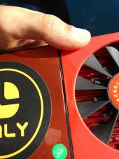
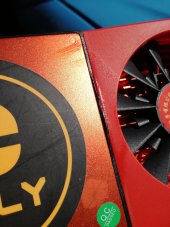
When i received the BMS it looked like it had another sticker beside the "Q.C. Passed" one, but it was removed. On top of that, the plastic between the cooler fan and the rest of the BMS, appears to be melted.
IMG_20210912_111057.jpg IMG_20210912_111125.jpg


I knew the return process would be a nightmare and after the extra €50 i had to pay at the costums and the 3 months i waited for it, i decided to at least see if it works.
It worked, but i tested it with a low curent and a short time interval. So not much of a test and i realize now i shoud have done a proper stress test.
But to be honest, I'm only drawing a small amount of current out of my system for short periods of time. For example, when i cook something, i draw around 40-50A for 10 minutes or less.
The solar charge controllers reach less than 40A peak.
The first problems appeared when my 150-70 Victron SCC started giving high battery voltage errors in the mornings. After alot of searching on what the problem might be with the SCC, i realized it wasn't it, it was the BMS. In the mornings, the BMS would incorrectly read the cell voltages and come up with a number of over 30V for a few minutes. I "solved" this problem by reducing the max absorption voltage on the SCC's from 28.2V, to 27.2V, because this error only happend when the battery was almost full.

The second problem i found was that the BMS was getting really hot even when i was drawing 10A for 30 minutes. And if i was drawing 30A or more for the same time, it was getting super hot, i couldn't even touch it. And the weird thing was, the cooler fan never started.

It finally died when i draw 100A for less than 10 minutes once. That was the first and last time i saw that fan spinning.

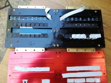
Because i was curious about the built quality of this BMS, which was supposed to take 300A, but died after 10 minutes at 100A, i took it apart, and to be honest, i was disgusted with it.
IMG_20210912_112403.jpg
IMG_20210912_112641.jpg
IMG_20210912_112852.jpg
IMG_20210912_112411.jpg

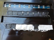
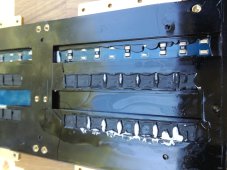
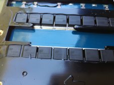
I found that the thermal pad wasn't even touching half of the MOSFET's, so not much of a heat transfer was going on between them and the heatsink. I doubt that black resin mould around the components melted when the BMS died, i think it was like that from the begining. It's not evenly distributed and it actually spilled on top of the MOSFET's, preventing a good heat transfer.
The top right MOSFET was swollen, and probably that's where it failed.

I'm not saying all Daly BMS units have this problem, this is just my experience with one of them. It probably was a faulty one, but someone gave it a Q.C. pass and they sold it as new.

Since then, I'm running my system with no BMS. I monitor my cell voltages regularly and they never drifted. I do plan on buying another BMS, just not a Daly.
 
Back
Top