diy solar

diy solar

DIY Vendor agnostic Smart Shunt & Victron Smart Solar MPPT data logger based on ESP8266

rin67630

Solar Enthusiast
Joined
Apr 29, 2020
Messages
1,068
Location
Nort-Rhine-Westphlia Germany
(Original old post replaced with something more representative of the current situation of my project)
I will maintain that first post current to give a first impression of the project at a glance.

My project Victron_VE_on_Steroids gets more and more functions.
It started an alternative logger for the Victron VE interface (MPPT Chargers and Smart Shunts)
It can now be configured as a very low-cost vendor agnostic Smarter Shunt as well
IMG_20240202_143042.jpg

The Smart-Shunt requirements on hardware are extremely limited:
- a shunt (that you probably already have, any shunt up to 75mV can be configured)
- an ESP 8266 microcontroller (~4$) (Wemos-D1 recommended but others do as well)
- an INA226 off-rail power interface (~5$)
- a 8-35V to 5V micro buck converter. (~2$)
- a few wires and some prototype case

The Victron logger requirements are even lower:
- an ESP 8266 microcontroller (~4$) (Wemos-D1 recommended but others do as well)
- a 8-35V to 5V micro buck converter. (~2$)
- a few wires and some prototype case

Optionally
- a snap-on OLED shield 64x48 pixels for the Wemos D1 (~5$)
- or a 128*64 I2C OLED display (~5$) much better, needs a few more wires soldered.

Everything is self-contained. The communication occurs over WLAN and is completely wireless. (no ground loops to be feared).
No additional computer or gateway required for permanent operation !

What do you need to get started:
Above mentioned devices
A computer.
Free Software: the Arduino programming IDE.
An access to Github to download the code.
You don't need an extensive programming knowledge: the program adapts to your situation over a few directives on the config.h and credentials.h files.
here an example:
Code:
//----------------------- HARDWARE OPTIONS ---------------------------------
#define AO_IS_NONE        // _NONE , _DOUBLEBATTERY , _HALFBATTERY, _PANEL, _POT
#define A0_MAX       15   // if A0 is used, define the voltage of the full range measure
#define D0_IS_NONE        // _NONE , _RELAY1
#define D5_IS_NONE        // _NONE , _RELAY2
#define D6_IS_NONE        // _NONE , _RELAY3, _VE_BLOCK, _VE_START_STOP
#define D7_IS_NONE        // _NONE , _RELAY4; _VICTRON
#define OLED_IS_64x48     // _NONE , _64x48 , _128x64
#define OLED_IS_REVERSED  // _IS_NORMAL, _IS_REVERSED To turn the display 180° if required
#define INA_IS_226        // _NONE , _226
#define INA_VBUS_IS_HALF  // _FULL _HALF   (when high voltage schematic is used)
//#include "MPPT_75_15.h"
#include "SHUNT_10A_75mV.h"
#include "LiFePo_13V_100Ah.h"

//----------------------- SOFTWARE OPTIONS ---------------------------------
#define WEATHER_IS_OWM  // _NONE , _OWM , _BME680    // (Source of the Weather Information)
#define DASHBRD_IS_NONE    // _NONE , _THINGER          // (Internet Dashboard)
#define TERM_IS_TELNET     // _NONE , _TELNET, _SERIAL , _SOFTSER // where do Menus and Reports occur: _SERIAL and D7_IS_VICTRON mutually exclusive )
#define UDP_IS_NONE        // _NONE , _SEND , _RECEIVE  // (UDP Inter-ESP Communication)
#define COM_IS_NONE        // _NONE , _MIDNIGHT         // Periodical reports to computer
#define ESP_UDP_ADDR   "192.168.188.64"                  // (IP of the receiving ESP)
#define ESP_UDP_PORT    4200  // (Port used to send/receive Values to other ESP)
#define COM_UDP_ADDR   "192.168.188.1"                  // (IP of the receiving computer for night reports)
#define COM_UDP_PORT    4200                            // (Port used to send/receive Values to other computer)
#define DEVICE_NAME    "ESP_LP"                         // Name of the device used as Hostname and at Thinger.io
#define DEVICE_NUMBER   0

But, if you feel in the mood to get your hands in the guts: I write code like an engineer, not a programmer: close to natural language to remain understandable to everybody.

Once compiled and uploaded, from your computer, you can access the device over Telnet, e.g. :
Code:
$ telnet 192.168.188.27
Trying 192.168.188.27...
Connected to steroids.fritz.box.
Escape character is '^]'.

Waiting for input
B
Battery Stats
Hour   |  00   |  01   |  02   |  03   |  04   |  05   |  06   |  07   |  08   |  09   |  10   |  11   |
Bat Ah | 12.63 | 00.00 | 00.00 | 00.00 | 00.00 | 00.00 | 00.00 | 00.00 | -0.00 | -0.02 | 00.01 | 00.06 |
Bat V  | 12.46 | 12.45 | 12.43 | 12.43 | 12.43 | 12.42 | 12.42 | 12.41 | 12.41 | 12.43 | 12.45 | 12.61 |
Hour   |  12   |  13   |  14   |  15   |  16   |  17   |  18   |  19   |  20   |  21   |  22   |  23   |
Bat Ah | 00.36 | 00.52 | 00.36 | 00.06 | 00.46 | 00.02 | 00.00 | 00.00 | 00.00 | 00.00 | 00.00 | 00.00 |
Bat V  | 13.28 | 13.95 | 12.96 | 12.57 | 12.79 | 12.56 | 12.51 | 12.50 | 12.48 | 12.47 | 12.47 | 12.46 |

V
Values Report
BatV:12.56 BatI:-0.03 BatW: -0.38 PanV: 17.52 PanI: 00.00 PanW: 00.00 LoadI: 00.00 LoadW: 00.00 IOhm: 0.0008
BatV:12.56 BatI:-0.03 BatW: -0.38 PanV: 15.27 PanI: 00.00 PanW: 00.00 LoadI: 00.00 LoadW: 00.00 IOhm: 0.0008
BatV:12.56 BatI:-0.04 BatW: -0.50 PanV: 15.23 PanI: 00.00 PanW: 00.00 LoadI: 00.00 LoadW: 00.00 IOhm: 0.0008
BatV:12.56 BatI:-0.04 BatW: -0.50 PanV: 14.75 PanI: 00.00 PanW: 00.00 LoadI: 00.00 LoadW: 00.00 IOhm: 0.0008
BatV:12.56 BatI:-0.04 BatW: -0.50 PanV: 14.58 PanI: 00.00 PanW: 00.00 LoadI: 00.00 LoadW: 00.00 IOhm: 0.0008
BatV:12.56 BatI:-0.02 BatW: -0.25 PanV: 14.43 PanI: 00.00 PanW: 00.00 LoadI: 00.00 LoadW: 00.00 IOhm: 0.0008

Waiting for input
W
Weather list :
Temp: 8.9°C Hum: 80.0% Press: 1028mBAR WindSpeed: 8.8m/s Direction: 230°N Clouds: 100% Summary: overcast clouds

Over Internet, using a permanently free account at thinger.io for up to two devices, you get a gorgeous dashboard to monitor your data.

1706883679695.png

And the project permanently evolves and gets new functions...
(I live in a condominium and cannot use a full blown solar installation, so the shown Voltage / Current values
in my examples are limited, but everything is scalable)

The regular version of the Smarter Shunt and Victron VE logger works with batteries up to 24V nominal.
I have an alternative hi-volt version available up to 48V too, but you need to find an adequate DC/DC converter able to handle up to 60V.

The software is completely free and open-source under creative common license CC BY-SA.
It is given in the hope to be useful, but I am NOT RESPONSIBLE IN ANY WAY OF DAMAGES WAHTSOEVER occuring from the use of my software.
The project is on GitHub.

Anybody wishing to join is welcome...
Please feel free to discuss at the end of that thread. Suggestions are welcome.
I also would love to get feed-back from people using other products with Victron-PE interface.
 
Last edited:
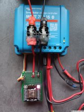
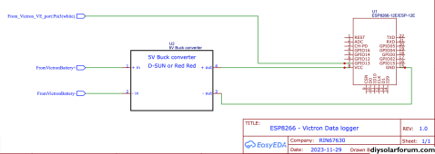
IMG_20231129_152948.jpg

The prototype board is only there to give some mechanical stability.
I have soldered a micro DC/DC converter behind the ESP module to feed it from the 12 V battery.

Code:
$ telnet 192.168.188.28
Trying 192.168.188.28...
Connected to esp-7b1476.fritz.box.
Escape character is '^]'.
BatV:13.8000 BatI:0.2100 PanV: 18.7900 PanW: 0.0030, LoadI 0.0000
BatV:13.8000 BatI:0.2200 PanV: 18.8100 PanW: 0.0030, LoadI 0.0000
BatV:13.8000 BatI:0.2100 PanV: 18.7900 PanW: 0.0030, LoadI 0.0000
BatV:13.8000 BatI:0.2100 PanV: 18.8100 PanW: 0.0030, LoadI 0.0000

Q

bye bye
Connection closed by foreign host.
 
I'd wager there would be quite a bit of demand if you wanted to sell this as a retail unit. Moving from short range BT to WiFi would be a big feature.
 
Do you happen to have one of those junktech shunts ?
There is a GitHub to get that data out into home assistant but I could never ever get it to work, I think I have DNS issues with my Wi-Fi extender and I got annoyed and just use the display.
 
What would be your preference for the next step?

All variants will have an internet Dashboard and statistics without additional computer/smartphone/subscription, but i have the choice of different hardware bases:

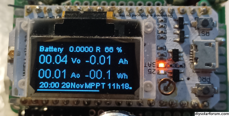
- ESP8266 (WemosD1) with the option to have a tiny monochrome 48*64 pixel piggy-back OLED local display?
(cheap, low power drag)
- HELTEC LORA 32 with integrated monochrome 128**64 pixel OLED local display and LoRa transmission ?
(cost around 20$, higher power drag, can work on WiFi and also on LoRa wireless transmission over a few KM/miles)
1701285252260.png
LoRa transmission would need a second receiver HELTEC LORA 32, but could operate onsite without WiFi coverage.
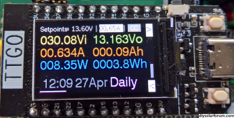
- TTGO 32-1 with a gorgeous integrated local 1.14″ IPS LCD 65K rich colour display giving 135X240 resolution.
(cost around 15$, highest power drag)
1701285063520.png

All these are pictures from my Drok/Juntek-on-Steroids project, from which I can recycle a lot of code...
What were your preference?
 
Last edited:
Do you happen to have one of those junktech shunts ?
There is a GitHub to get that data out into home assistant but I could never ever get it to work, I think I have DNS issues with my Wi-Fi extender and I got annoyed and just use the display.
What do you mean with Junktech shunts?
Please give references
 
For example
My struggles
 
For example
That looks to be an Android closed source manufacturer app.
Nothing in common with my stuff, which is open source ESP8266/ESP32 code that every body can modify/extend...
 
It is already WiFi !
I won't sell anything. I am retired and have enough money to live.
The next steps will be to add an Internet dashboard.
Sorry I meant moving from the limited range of the BT in the Victron smart scc to WiFi via the ve.direct port.
 
My struggles
I've heard of Home Assistant and also the option to run Venus on a Raspberry pi.
My approach is to limit the necessary hardware to a strict minimum: No computer at all, not even a Raspberry Pi.
One ESP controller and that's it: you get in touch with your Victron from every browser on the earth.
 
Have you done any ESP8266 interfacing with Epever MPPT controllers?

I've been using ESP8266's here for all sorts of projects (GPS clock, mailbox alert, weather display). I have many Wemos D1 Minis around here.

I have a Victron 150/45 in the mix now and would love to be able to remotely see what it is up to. Right now the Victron app and what the 150/45 is making production wise is not jiving with my Victron Smart Shunt. Being able to include the Epever 4215bn would be nice too.

No preference on displays other than I already have a number of 1" monochrome OLEDs
 
Have you done any ESP8266 interfacing with Epever MPPT controllers?
No, Victron is my first start with commercial MPPT devices.
I use to make my MPPT controllers myself. :p
I've been using ESP8266's here for all sorts of projects (GPS clock, mailbox alert, weather display). I have many Wemos D1 Minis around here.

I have a Victron 150/45 in the mix now and would love to be able to remotely see what it is up to.
Currently supported by the original Autor Datjan are:
// "MPPT 75 | 15" tested with FW 1.56
// "MPPT 100 | 20" tested with FW 1.5 / 1.56
// "MPPT 100 | 30" tested with FW 1.59
I am not aware how different the protocol of the stronger devices is. Probably only a few keywords more...
You might need to dig into the doc and add these definitions to config.h, which is surely no rocket science.
I'd love to get your feedback to get more devices supported.
Right now the Victron app and what the 150/45 is making production wise is not jiving with my Victron Smart Shunt.
Smart shunts could be added as well, if they have the VE port. Same procedure: edit the config.h.
Being able to include the Epever 4215bn would be nice too.
That beast has surely not the VE serial protocol. Let us stick to that one for the time being.
No preference on displays other than I already have a number of 1" monochrome OLEDs
OK, vote registrated.
 
Currently supported by the original Autor Datjan are:
// "MPPT 75 | 15" tested with FW 1.56
// "MPPT 100 | 20" tested with FW 1.5 / 1.56
// "MPPT 100 | 30" tested with FW 1.59
I am not aware how different the protocol of the stronger devices is. Probably only a few keywords more...
Caveat emptor: I just have noticed that the newest firmware seems to have harmonized the VE protocols.
My MPPT 75/15 with firmware 1.63 works fine with the definitions of MPPT 100/30. (but not any more with the old definition)
 
Last edited:
Sounds interesting. I currently use an ESP32 that has two hardware serial ports (rather than the 8266), so avoiding reliability issues with SoftwareSerial.

The galvanic isolation would be really useful, but I only have a Victron Smart Shunt, which unfortunately doesn't have WiFi - only VEBus and Bluetooth. Do you know if your WiFi / Telnet solution might work over Bluetooth as well?

Edited to add... sorry, I was having a blonde moment ?‍♀️. So, what you are doing is using the ESP8266 to bridge VE port to WiFi, i.e. no galvanic isolation between Victron and the ESP. Then, in that case, it is already similar (on the Victron side of things at least) to the code I am using, based on the esp vedirect code from Ralf Lehmann & Simon Jones. See link below if it's of interest...

I am not currently fixed whether i will use an ESP8266 or an ESP32. The later has interesting variants with built in displays, but draw more current.
I am more on small island DC systems without grid and the residual consumption is crucial.
Interesting is also the Heltec-LoRa 32, which as a LoRa radio. With a pair of Heltecs I could make a remote system that broadcasts over a few miles.
The powerful Victrons and some smart shunts are using CanBus, which is exceeding the capabilities of an ESP 8266.

For me the galvanic insulation is always between the ESP and any computer which may control it. The ESP is powered from the local battery.
Software is loaded over OTA.
 
What would be your preference for the next step?

All variants will have an internet Dashboard and statistics without additional computer/smartphone/subscription, but i have the choice of different hardware bases:

- ESP8266 (WemosD1) with the option to have a tiny monochrome 48*64 pixel piggy-back OLED local display?
(cheap, low power drag)
- HELTEC LORA 32 with integrated monochrome 128**64 pixel OLED local display and LoRa transmission ?
(cost around 20$, higher power drag, can work on WiFi and also on LoRa wireless transmission over a few KM/miles)
View attachment 180309
LoRa transmission would need a second receiver HELTEC LORA 32, but could operate onsite without WiFi coverage.
- TTGO 32-1 with a gorgeous integrated local 1.14″ IPS LCD 65K rich colour display giving 135X240 resolution.
(cost around 15$, highest power drag)
View attachment 180308

All these are pictures from my Drok/Juntek-on-Steroids project, from which I can recycle a lot of code...
What were your preference?
My vote is for the TTGO 32-1 , maybe with a display on/off option to save a few watts?
 
Now that I have the Victron data running, it's time to move to the full project:
Victron_VE_on_Steroids.
I decides to go further and provide additional information derived from the given data:
  • Power values where not provided
  • Battery monitoring (internal resistance, SOC)
  • long time integrations (battery capacity, Coulomb integration etc...)
For these last functions one need a data persistance that survives resets and also the ability to enter some variables.
EEPROM is... Bah. Not really useful if you need to swap ESP devices.

So comes the time to introduce thinger.io :
Thinger is a dashboard SaaS that lets you use two devices free of charge. Forever.
Thinger does not primarily use MQTT. It uses a proprietary JSON based transmission directly from the device to the servers of thinger.io
You don't need a broker and you are not limited by broker's restriction on how fast you transmit data. Sub-second updates are not a problem.
And Thinger provides Device Properties storage, that is much more powerful than EEPROM.
Thinger does not need a Grafana server to build Dashboards. You can do that directly on-site.

So the bottom line: with thinger.io you don't need anything more than your ESP device and a WiFi internet connection.
No additional computer, no broker, no subscription. No cost (for 2 devices).
You get:
  • gorgeous dashboards, (up to 4 free of charge)
  • buckets to store long term data (up to 4 free of charge)
  • device properties (up to 4 free of charge)
I have used Thinger for a couple of other projects like Drok-Juntek-on Steroids, which is a Home Brew MPPT controler built on commercial buck converters.
https://github.com/rin67630/Drok-Juntek-on-steroids
(you can have a look there to see the dashboards and onboard screens)
I can re-use a lot of code from this project on Victron-on Steroids.

So comes time to introduce Karajan:
Karajan is a framework and collaborative scheduler that I wrote years ago to facilite my developments on Arduino/ESP devices.
I am an engineer, not a programmer.
I hate it, when programms are written in Volapük, (my expression to describe code that has nothing left with natural language).
Karajan is written for flexibility and readabilty: it works intensively with computer directives to adapt the code to different situations/ configurations. With Drok-Juntek on steroids I have somewhat exaggerated with the configuration options...

The Arduino IDE has a great feature: tabs.
Karajan makes use of these tabs features of the Arduino IDE to split the code like an orchestral partition into clear sub-parts
for each instrument (purpose):
-Configuration
-Credentials (not to be published)
-Libraries and global variables
-Network functions
-User functions
-Setup
-Menu for user interaction.
-Fast data (to be processed at 125mS pace)
-Slow data (to be processed at 1S pace)
-Statistics (to be processed at 1S pace)
-Display (to be processed at 1S pace)
-Serial communiction (to be processed at 1S pace)
-Wireless comminucation (to be processed at 1S pace)
and finally the scheduler itself.
With that organisation, the developer can easily jump to the desired part of the code to make a correction without searching pages of code for the right place.
All jobs to be processed at 1S pace are distributed in 125mS slices, so to distribute the processing time evenly and avoid to do everything at the same time.
Karajan provides a measuring/reporting function for the time taken by every task.
It provides all initializations for WiFi and time synchronization, so you can just start with your part.
It provides variables to do a lot of stuff at given times and gives global variables as e.g.
Bytes:
  • Second, Minute, Hour...
    Boolean:
  • NewMinute, MinuteExpiring, NewHour, HourExpiring and so forth..
    so you can write code to be executed at given times in natural language.
For the time being Thinger is not yet integrated, i am working on the computation of the battery's internal resistance.
For the next steps (long term integrations, i will need Thinger.
But the project develops fast, it's mainly cut/paste from my other project, and some code cleansing....

If someone has routine for a good evaluation of the SoC for LiFePo i'd appreciate to integrate it onto my project.
 
Last edited:
Back
Top