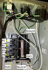
I am asking for review of my thinking. my solar system education requires constant oversight.
Below is a picture of a Siemens TL137US Talon Temporary Power Outlet Panel with a 20, 30, and 50-Amp Receptacle Installed, Unmetered Gray.
Apologies for the U.S. centric assumptions such as wire color. I am only talking about 120V 60Hz single phase AC power here.
Please assume correct wire sizes will be used. Making the below description was difficult, I tried to be precise.
AAAA. Utility provides three residential connections, Hot1, Hot2 (these are out of phase by 180 degrees), and Neutral. The ground is a return line to Earth made at the home. At my home it is a pipe driven into the (dirt) ground the meter rests on.
AAA. A primary panel has a connection (is continuous) between the ground and the neutral buss bars.
AA. A secondary panel does not.
A. GROUND (labeled) when hooked up, is a bus that will be continuous with the ground of the Utility and Earth (the conducting conduit that the meter is attached to). There is no Utility Ground wire, it is made using a conducting pole driven into the ground.
B. HOT1 and HOT2 are where the Utility hot connects/inputs to the panel. As a single phase system, these two points are equivalent (thinking-wise). For a 240V panel (thinking-wise) they have 240 volts between them.
B2. HOT1 and HOT2 are 180 degrees out of phase, so using either have 120 volts potential, but between them have 240 volts potential.
C. Power output of 120V 60Hz 50 amps can be made with a circuit consisting of three wires:
- A hot (Black wire) attached to the point at the (yellow star) screw by B1
- Neutral attached to the Neutral Bus,
- Ground (green wire) attached to Ground bus.
D. Power output of 240 volts 50 amps can be made by
- A hot (Black wire) attached to the point at the (yellow star) screw by B1
- A hot (red wire) attached to the point at the (yellow star) screw by B2
- Neutral attached to the Neutral Bus,
- Ground (green wire) attached to Ground bus.
Thanks for your patience and comments.

Last edited:


