diy solar

diy solar

Eg4 LL Guidance

RL419

New Member
Joined
Apr 8, 2022
Messages
6
Hi,

I am gathering materials to complete a 120v off grid solar system for my small cabin and have many questions that I hope the community can help with. I worked with Lori at practical preppers and got as much as I could they had to offer for my setup.

My system will comprise of 3 EG4 LL 48v batteries in the EG4 rack, the EG4 6500 (which has yet to ship,) and two strings of 6 panels in series.

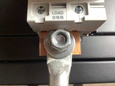
My first question is regarding the connection of the 4/0 AWG from battery rack to the 60v 200 amp breaker (They sent two breakers but dont I only need one for the + line right?) There is no way this 4/0 is going to fit in the mechanical lug. I am thinking about removing the mechanical lug on the breaker and connecting directly the 3/8 lug that is on it by the screw and nut with a bigger one and torquing it down. Is that fine to do?

2nd option would be to run the 4/0 to a busbar and 2/0 into the nader...I need to buy some 2/0 to go from the breaker to the inverter anyway. Which option would you go with?
Nader.jpg
 
That breaker is rated for 200 fault amps that means you should only run 160 service amps through it.
I've heard reports that the mechanical lug is connected to the copper adapter with a threaded screw.
The reports say that the threaded screw does not secure the mechanical lug well enough to stop the lug from moving.
 
Anyway mech lugs for 4/0 usually have 8mm(5/16") or bigger holes.
 
Your first option plan looks good to me. Screw and nut as you say or bolt and nut.

I wouldn’t do the second option.

Having LOAD embossed on the bottom of the breaker implies this is a polarized breaker although that is not clear to me from the info you linked.
 
Thanks for the feedback. It is much appreciated. Will recommended this breaker as an alternative to a class T 200 amp fuse in his 48v blueprint. I am still waiting on the inverter to arrive. I will post more as my project progresses.
 
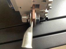
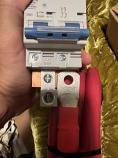
I just ran into this problem yesterday on my install. I prefer a crimp instead of the included aluminum mechanical lug and I wasn't convinced I could fit the 2/0 welding cable in there anyways. I removed the copper from the breaker, drilled and tapped for 3/8 16 (for added connection) and then added hardware. I'm thinking it's getting a way better connection than the included lug but some actual adult supervision on this would be great! I haven't torqued it down yet but it "feels" WAY better.
IMG_0602.jpgIMG_0601.jpg
 
I just ran into this problem yesterday on my install. I prefer a crimp instead of the included aluminum mechanical lug and I wasn't convinced I could fit the 2/0 welding cable in there anyways. I removed the copper from the breaker, drilled and tapped for 3/8 16 (for added connection) and then added hardware. I'm thinking it's getting a way better connection than the included lug but some actual adult supervision on this would be great! I haven't torqued it down yet but it "feels" WAY better.
View attachment 118230View attachment 118229
What is your concern?
 
Thanks for the response! Current flow and stability over time being equal to or greater than the OG lug.

Well you lost a bit of copper when you drilled out the lug but its probably net win because the new stud will fasten better than the wimpy joinery of the mechanical lug.

Does the copper comb busbar still bottom out in the cage clamps?
Did the flat washer have to be ground flat for clearance?
Can you get a socket on the nut and/or bolt?

I'm trying to determine why SS didn't do more beefy joinery.
That's what I thought for the copper loss. Glad to hear my shade tree eyecrometer math isn't way off.
Yes, the copper comb busbars still bottom out in the cage clamps.
Yes, I had to grind some of the flat washers down a mil or two for clearance on those cage clamps.
Clean as a whistle for socket on top and wrench for the head in back to support those soft copper threads JIC.

I'm not sure why SS didn't beef it up, but at least they got close enough for me to finish it up! :D I was about to go pick up some 3/0 copper mechanical lugs from HD but luckily I got to think about it for the afternoon before coming up with this.

Should I be using stainless hardware for the 3/8 16 items? These are all zinc.
Zinc should be fine for stationary climate controlled environment.
 
So your battery is connected to the load terminal correct on the relay?.
 
Last edited:
Back
Top