diy solar

diy solar

EG4-LL (version 1) 24v 200A and WakeSpeed Alternator Controller CAN communication

VanLuna

New Member
Joined
Aug 4, 2021
Messages
21
Has anyone used a WakeSpeed with the version 1 EG4-LLs?

--- answer --
April 2023: I want to provide an answer to the original question up front to save future readers from reading all this.
No. The V1 will not work with Victron without a V2 as the master (battery ID 1) in the system.
More details and discussion about V2s below ....

----- original post ----
I want to confirm you have the v1 working with the CAN input on the WakeSpeed.

I'm having a chat with the kind folks at American Power (alternator) about adding a 24v Alternator to my Ford Transit 350 EcoBoost and this concern was expressed:
"Will again emphasize the need for not just CAN but the ability of the BMS to communicate outbound so to be able to have the alternator disconnect prior to an emergency cutoff of charge should it occur. Without that ability you will have a large voltage spike occur when the alternator would lose the 24V battery sense and try to recreate it in a flash. The large voltage spike will likely take out the alternator and/or regulator that would not be covered by warranty."

So if someone is already doing this, that would be good to know.

Thanks!
 
Last edited:
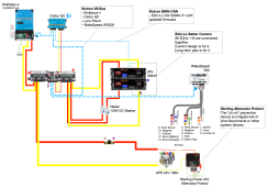
I've done more reading and have made a sub-system drawing I thought others might like to see. This is still a "draft". I'm in discussions with Signature Solar, WakeSpeed, and American Power (alternator) about the whole thing...

One thing I have learned that I did not know before is that the battery connects to the BMS-CAN on the Cerbo GX.
I had thought it was all one CAN bus.
Also, Signature Solar says V1 EG4-LLs can be updated to communicate on the Victron BMS-CAN as per this video about the V2s:

With those things now understood, here is a brief run-through.
  1. On the VE.BUS we have all the Victron components and the WakeSpeed (and the terminators).
  2. On the BMS-CAN we have the EG4-LLs with. Updated firmware.
  3. All the EG4s are interconnected over their builtin battery comms.
  4. A Sterling Alternator Protect is added to prevent me from doing anything dumb, or from any other potential failure cases like loose wires or CAN comms failures.
The last thing I'm looking to confirm is that the EG4's output on BMS-CAN meets all the needs of the WakeSpeed.
There is a non-zero chance that the EG4 works with the Victron components, but is missing something the WakeSpeed needs.
I think its unlikely, but I want to verify before buying and American Power wants to sign off before the sell me anything and support it.

1674174096619.png
 
Doesn't seem like anyone here has experience with this setup, I posted a similar question on the Victron forum... I'll post back if I learn anything new.
 
If you can go to Facebook look on Prevost bus, there is a gentleman named Aaron that put in a system similar that you want to do. He is also on Youtube under Camp Prevost.
 
Thank you @Partsjockey They are doing EXACTLY what I'm doing.

 
Hello all. Was pointed here by email. I believe you are on the verge of cracking the code I have been trying to - getting the EG4 to act as the BMS within the Victron gear and communicate the same to the WS500. My bus is still in storage so this is my next step to work towards. I purchased the EG4 to Victron cable - but had asked SS for what to do then - which port to plug it into, what Cerbo settings etc - but have had no response. I do have the WS500 plugged into the Cerbo via CAN and it does show WS500 when the bus is turned on but I don't believe I have the settings correct - it doesn't appear to show the correct data. Also be forewarned - the WS500 has 100 of settings - I cheated and used max wattage until I feel confident with the other settings acting correctly. My last trip I took I did notice the Cerbo alarmed over voltage - the WS500 ramped up to high (28v vs 26.7) - I am not completely sure why - I don't believe it did that last fall - so I am assuming I must have entered something wrong. I also ended up purchasing a cheap PC to interface with everything - using parallel's on my Mac was horrible at best. So long story short, I have the proper cable now, have a PC but need some better weather to bring the bus home and work on settings - one reason why I haven't pushed SS and WS for answers back.

Another item I was able to overcome was the Victron inverter capacitor charging with the EG4 (turning the system on). I have been wanting one battery to do it, so I purchased the V2 battery but it still fell short trying to start my 2 inverters. My success came in starting one battery (it ramped to about 18v) then immediately starting the next (it took the 18v and ramped to 26v). I then reset the remaining batteries and everything worked well. I had been manually charging the caps prior to this.

In the diagram above, don't forget a 24/12 step down transformer to run any 12v loads - I used Victrons 70amp and set the voltage to 13.1 (It was actually set there from the factory) and everything works great. I do have a large switch and fuse after but before the loads.

In regards to updating the V1 software to communicate with the V2, I have seen that done but felt the video from SS lacked the details. With having a PC now, I planned to do that this spring as well.

My system currently works with each device having the proper settings but would like to have the EG4 tell the WS500 and Victron what to do (or at least communicate what its doing).
 
To answer your first question - American power is referring to a load dump - basically the BMS within the EG4 cutting out while the alternator is providing a charge. I found the Sterling Alternator protection device and it was made to handle that (I am trusting them). When the voltage spikes to almost infinity, the amps will ramp down to nothing - so the thought is the SAP will dissipate that voltage spike or blow itself up - an $80 insurance device. If you set your WS500 settings below the EG4 cut off's, it shouldn't go there in the first place - but anything can happen.

One other thing to note are the EG4 charge settings.

I owe this to the guy on "Off-Grid-Garage" but tested myself and use the followings settings on all devices;
  • 3.1v or 24.8v should be the lowest cutoff
  • 3.3375v or 26.7v is the LifePo4 resting voltage - so I use this as my float setting
  • 3.45v or 27.6v - I use this for the absorption voltage
  • 3.456v or 27.65v - this is the max voltage I charge to - so this is my bulk setting
Anything any higher than 3.456v per cell is a waste of time, energy and possibly degrades the cell. Some believe this is what causes the cells to expand, and also causes micro cracks within the cell - possibly degrading the cell over time. My Victron's will bulk to 27.65 - I set this to 100%. If you watch the charge curve, the amps really back down to almost nothing and the voltage starts ramping very high - for a long time - trying to stuff everything it can into the cell. The same is true when discharging. The 3.1v per cell keeps the cells at a relatively flat curve. Anything less and the voltage really starts to ramp down - without many amps coming out. So the thought is keeping within these settings should preserve a great battery chemistry even longer.
 
I want to say one thing and then we'll keep going with the V2 discussions.
No. You cannot use EG4-LL Version 1 batteries with Victron and Wakespeed.
That was the original question I posted and I want to write it down for future readers.
The answer is no; not in any supported way with communication between all systems.

EG4-LL Version 2 Systems

BMS DC Disconnect

In the discussion above where we're talking about the Sterling and load dumps. The critical feature we need to know if the EG4-LL's BMS supports is called "advanced notification of pending DC disconnect". I'm waiting on a clean Yes or No answer from Signature Solar on that item. In theory, the Sterling _should_ protect the alternator regardless. American Power the alternator mfg I'm working with is pretty adament DC Disconnect _must_ be supported. More to come ...

Charge Profile
I'm working to mockup a charge profile on my own with the WakeSpeed iPad app to get reviewed. You need to be in Expert Mode in the app to get to all this.

Battery Charging from the EG-4 LL Manual (PDF) on page 9.
1. Bulk/Absorption: 28.1V (+/- .2V)
2. Float: 27V (+/- .2V)
3. Low DC cutoff: 23.5-22V*
4. Battery Charge Temperature Range: 32°F - 113°F ( 0°C - 45°C )
5. Battery Discharge Temperature Range: -4°F - 122°F" ( -20°C - 50°C)

WS Config for my system

Code:
#
#     Battery system: Generic, 24v, CPE#8 LiFeP04, 2, 200
#     Alternator: APS, 185H-24 (American Power Systems)
#     Alternator notes: 24V - 185A.
#
$CCN: 0,1,70,1,1,1,0,4,0,0,0.0,0@
$SCA: 0,120,0.62,0.46,0.31,0,0,0,10000,0,0,30,0,8,100@
$SCT: 16,2.388,0,0,0@
$SCN: 0,MyVan,1234@
$SCO: 8,0.8,2.0,0,0,0@
$CPA:8 16.5,0,0,0@
$CPO:8 0,0,0.0,0@
$CPF:8 16.5,0,0,0,0,0.0,0@
$CPP:8 0,0.0,0,0.0@
$CPE:8 0.0,0,0,0@
$CPB:8 0.0,0,0,45,0.0,7,42,25,200@

@campprevost your Alternator would be different, but would you be willing to share your WS500 Config settings with us?
 
Last edited:
I want to close out this thread.

After many months of back and forth with EG4\Signature the answer is no there is no supported path to use EG4 Batteries with Wakespeed.

I know people are doing this and using an alternator protector, but that is relying on a fault protection for what should be a well supported communication between the BMS and the Alternator regulator.

I am not chosing to go that route and switching to the Victron Lithium batteries.
 
Since you guys are using Wakespeed, I'm curious have you measured cable temperatures at the alternator positive output stud?
I installed a full Victron system for a customer, including 4 x 330Ah Victron 12V batteries (+ 2 3VA inverter chargers, 1500W solar, etc). I fired up the Wakespeed for the first time today after having the Large Frame Leece Neville rebuilt and the brush adapters installed.
I was seeing 190 Amps in to the batteries from the alternator (maybe gross output of 210). Most of the 20' to 25' cable run is 4/0 x 2. An 8' run from the alternator to the DC fuse / junction box is 1 x 4/0. I was seeing 167F (seemed to be climbing) on the terminal and stud (hard to distinguish with my infrared temp gun).
This seems too high to me.
Any thoughts?

I had two ideas:
1. Move the temperature probe thermistor to the positive terminal stud on the alternator. This is probably temporary solution (see #2).
2. install another 4/0 cable run to the junction box.

Thank you,
Doug

This isn't the cable temps but the alternator temps which should be around 200f before the wakespeed starts throttling. The wiring at the alternator is going to be hot since copper is a great conductor of heat. If check the temp of the wiring a few feet back and see what it is. Regardless I'd use wiring rated for 90c (194F) as ambient engine temps can be above 60C not even accounting for the alternator being a heat source.

The wakespeed temp probe is to monitor the alternator temp not the wire temp.
 
Hi. Agree with all that. I was collecting my own data not a realtime dashboard from Wakespeed.

I measured the cable terminal temp with an infrared gun after manually checking different points and connections for hot spots.
I just don’t like the cable terminal at the alternator positive post at +60F from that of the alternator housing. The alternator housing was 100F after 15 minutes of running.
Thank you.
That's because the copper wire inside the alternator is the hot part which I believe is what the positive stud is connected to. The housing is designed to help dissipate the hear.
 
HMmm. I appreciate your thoughts.
The alternator builder said the hottest part would be the back of case behind the diodes. He does all the local fire truck and military alternators. He doesn’t know LiFePO4 batteries. But Wakespeed takes care of that.
I probably will add a second 4/0 cable just to spread the load and maybe design a thick large diameter aluminum threaded nut that would serve as a heat sink and offer more cooling surface area. This sits 24” from the hydraulic radiator cooling fan in this bus. So gets lots of airflow. It will blow your hair back.

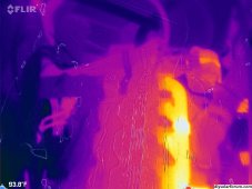
Here's my old rv engine and the hottest part are the copper coils in the middle. The frame of the alternator is steel so will take a long time to heat up.

Get 90c wiring. 190a is a lot but I don't think that's the issue
 

Attachments

  • FLIR_20220904_022412_801.jpg
    FLIR_20220904_022412_801.jpg
    911.5 KB · Views: 3
Back
Top