diy solar

diy solar

EMT for DC PV inside the house. Why?

Pull the pipe with the pv10 wires and put it through someplace else. Or pull the pipe and then feed it through from the other end.

And, Scott wouldn't have done it that way in the first place. He would have beamed the pipe into place.
You're right. I'll need to cut the wires. Do it right. Splice the wires. Not that big a deal overall I guess. Just need to stop looking for a quick fix.
 
You're right. I'll need to cut the wires. Do it right. Splice the wires. Not that big a deal overall I guess. Just need to stop looking for a quick fix.
Just splice them correctly for where they are and sealed for water intrusion. Generally I don't think much of standard wire nuts or Wago connector. I've used way to many wire nuts and way to few wago's to give advice on the subject, so take it with a grain of salt.

Someone will pipe up with the right connector for the job I am sure. I would make sure the individual splices are water tight and put them in a water tight box as well.
 
Now considering the splicing, I went and double checked my plan to use wagos on my thhn PV circuit. Apparently wago 221's are only rated for 450v? I didn't realize. But the classic 222's are rated for 600v.

I guess I have another digikey order to place.

Edit: Wait, actually both are spec'd for "450v nominal" and 600v UL max. Hmm, good enough for me I think.
 
But I would still wonder if you want to address the transition, if you can't pull the wires all the way back out. I'll admit that I'm a little skittish about the splices so I'm only doing them in outdoor jboxes away from the house. Everything indoor and through the PVC transition will be continuous.
 
But I would still wonder if you want to address the transition, if you can't pull the wires all the way back out. I'll admit that I'm a little skittish about the splices so I'm only doing them in outdoor jboxes away from the house. Everything indoor and through the PVC transition will be continuous.

This would be the MUCH prefered method verse splicing. I would only splice if there is no other choice. If you can pull it from one end or the other tie a string/rope to the wires before you do an use that to pull the wires back.
 
Last edited:
I just ran the calculation for 10awg PV wire 100ft long with 140vdc and 25amps - shorted at the midpoint - seems reasonable to me..... it takes 0.96 second for the jacket to melt. Assuming the breaker blows someplace no harm other than needing new wire. This assume the pv jacket is high cross-link polyethylene (XLPE)

For THHN the jacket melt time is 125 second. This jacket is PVC and has a much higher melting point.

In both cases it would take a bit over 2 hours to melt the wire in two. Say your breakers are at the house the solar panels are feeding the short. If your breakers are at the solar array the wires would pop there and hopefully not blow up the MPPT.

Interesting things that turn up when I ask questions and do the math. What does code say about this? Do the PV wires have breakers at both ends to cover all cases?
 
If your breakers are at the solar array the wires would pop there
How would a breaker trip though is the problem. Like for my string of 8 Qcells 480w, the MPP current is 10.59 amps, and the short circuit current is 11.58 amps.

So there's no way to protect against a short with an OCP device. If I put a 10 amp fuse it would blow during normal operation, and a 15 amp would not blow during a short. I don't believe you can try and get in the middle with an 11 amp fuse either, because the MPPT can suck short circuit amps out of the panels while it's searching for the MPP.

What voltage does that run? scratch that - about 330volts?

Looks like it takes about 2 minutes to melt the insulation at that voltage and current - if I am off with my guess lemme know.

And as a way to prevent it - nothing is ever easy. Which is why it needs to be inside EMT :)
 
I think there is the potential to cause more problems by cutting and splicing wires than there is in just leaving them alone now.
And I can tell you the rule has nothing to do with the voltage.
 
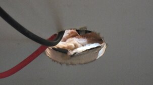
Nice discussion. Thank-you everyone. Now, my dilemma, since I now see the importance of EMT, is to decide if I want to fix the errors that I made when I brought the PV wires into the house. The external PVC looks beautiful, to include slip couplings. From the inside, it also looks nice. The EMT came out great. However, the transition from PVC to EMT is in a nearly unreachable location, so I let the PV10 stay without any PVC-to-EMT transition box or adapter. The PV10 goes about 6 inches through the wall without any protection. Stupid, I know, now. As crazy as it sounds, I might be able reach in that small space and wrap the wires together with foil. Kludgy and shameful, and no inspector would ever pass it, but we don't do much for inspection around these parts. Thoughts, including shaming, is appreciated!
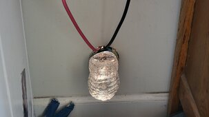
Feel no shame. My temp setup, got sick of taking the batteries outside every day to charge.

20240401_143104.jpg

20240401_162502.jpg
 
This would be the MUCH prefered method verse splicing. I would only splice if there is no other choice. If you can pull it from one end or the other tie a string/rope to the wires before you do an use that to pull the wires back.
Yup. I'll pull the wires and do it right. I just hate to go back, as a matter of principle. In this case, the time to kludge it is only a bit less time than doing in correctly. I'll need to pull the 4 wires and ground from the grid tie, pull the two spare pv10 to the grid tie. Pull the 4 wires and ground from the off grid. Take down the EMT and extend the ends into the tight space using a jbox of some sort. Not that bad, if I had done it correctly in the first place. Still wouldn't have been easy, but if I take my time, it certainly is fixable.

On a positive note, nearly all of the EMT and hangers and adapters, etc. can be re-used as-is.
 
Though code requires the DC PV wires to be in EMT (or some similar metal enclosure, I think), does anyone know the "why"? Other than, "because NEC code requires it", is there any logical reason why? How is EMT safer than PVC? If anything, it seems like PVC would reduce any shock hazard.
Code says:

"Where PV system dc circuits run inside a building, they shall be contained in metal raceways, Type MC metal-clad cable that complies with 250.118(10), or metal enclosures from the point of penetration of the surface of the building to the first readily accessible disconnecting means."

Note the "inside a building" clause. All the proposed reasons don't talk about the fact PVC conduit would be okay OUTSIDE the building. Why is PVC okay outside and metal required inside if the issues indicated would exist in PVC regardless of being inside or outside?

In other words, what changes when PV wiring goes inside such that metal is now required?

Mike C.
hwy17 (comment #4) hit the nail on the head, I think. Great discussion follows from #4. In a nutshell, a short from + and - inside the EMT could start a fire, but the fire would be contained inside the EMT. If PVC was using inside the house for the PV, the house could burn down. Key point is that there isn't a way to really put a usable fuse on a solar panel that would blow if the panel's wiring shorts inside the EMT. The panel will continue to provide ~10A or whatever it can, until a wire melts enough to prevent current flow.
 
The panel will continue to provide ~10A or whatever it can, until a wire melts enough to prevent current flow.
(1) wouldn’t you notice that the array isn’t producing any real current, or it would have wild swings?
Perhaps not in time for the fire, I know.

(2) I have GFPD to detect shorts from PV+ to EMT ground, but don’t other AiOs have arc fault detection for this issue?
Not that I would rely on that to protect the home

FWIW, I ripped out the nice PVC in my crawlspace and replaced it with EMT, and I sleep better at night.
All PVC outside, however.
The arc fault detection would shut down the inverter, but it wouldn't prevent the flow of current from the string that was causing the arc. EMT is the way to go!
 
I’m not bringing higher voltage DC into my cabin without rigid conduit.
Me neither, now that I've learned more about the reason. I just wish that I had done it right the first time. Living and learning with 480 vDC is going to kill me one of these days. Maybe that is why my wife lets me play with this stuff so much?!
 
Back
Top