Hello you all. I installed a small solar off grid system in my home but for some reason my solar charge controller will never get more than half the watts of my solar aray. I have 2x250w panels on my roof in series.My SCC is Epever 4210an.Wires are 6 gauge from the solar aray to my SCC about 30 foot long. I know.... too tick. When I measure the amps of the solar array I get 65 volts and about 9 amps but when the cables are connected to my SCC it will settle on 44 volts and 6 amps which is about half the watts. I am sorry if I sound silly but I don't have any other experience with solar or electricity before.


You are using an out of date browser. It may not display this or other websites correctly.
You should upgrade or use an alternative browser.
You should upgrade or use an alternative browser.
Epever harvesting half watts
- Thread starter asenov13
- Start date

Rednecktek
Solar Wizard
In series? You should be getting about twice that voltage. It sounds like a connector issue almost.
So when I measure the with multimeter I get 65 volts. When I re-connect the pannels to my SCC it detects 65 volts at first but than drops the volts to 44. I am thinking... if the SCC is limited by the wire from it to the battery.
Now is 10mm2
Now is 10mm2
Last edited:
efficientPV
Solar Addict
- Joined
- Sep 24, 2019
- Messages
- 1,367
Limited by shade or something else, not wire. You have measured 65V open circuit and 9A shorted. That tells me nothing other than it is connected. What does the panel label say?
The label on the panel say like 8.3amps or something. So the panels do what they should as the panels in series are 65 volts and 9 amps but my problem is the reading on the SCC. I only guess that the SCC even if it gets 500 watts from the panels will not output the same and I guess the numbers on my MT50 is the power that will go from the SCC to my battery. I just dont get where I lose half of the pannels watts.Limited by shade or something else, not wire. You have measured 65V open circuit and 9A shorted. That tells me nothing other than it is connected. What does the panel label say?
What is the battery state of charge? If the battery is near full it will take a limited amount of current - normal.
What is the panel orientation to the sun? Unless it's a clear summer day with direct facing to the sun, you won't get full wattage output - also normal.
Open circuit voltage is different than connected voltage - also normal. If Voc is 65V then 44V connected sounds about right.
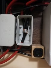
What is the second set of breakers next to the inverter for? What are the little white boxes to the left of it? Have you measured voltage/current before and after these connections?
What is the panel orientation to the sun? Unless it's a clear summer day with direct facing to the sun, you won't get full wattage output - also normal.
Open circuit voltage is different than connected voltage - also normal. If Voc is 65V then 44V connected sounds about right.
What is the second set of breakers next to the inverter for? What are the little white boxes to the left of it? Have you measured voltage/current before and after these connections?
How are you measuring amps from your solar panels?...When I measure the amps of the solar array I get 65 volts and about 9 amps but when the cables are connected to my SCC it will settle on 44 volts and 6 amps which is about half the watts. I am sorry if I sound silly but I don't have any other experience with solar or electricity before.
What is the battery state of charge? about 70%What is the battery state of charge? If the battery is near full it will take a limited amount of current - normal.
What is the panel orientation to the sun? Unless it's a clear summer day with direct facing to the sun, you won't get full wattage output - also normal.
Open circuit voltage is different than connected voltage - also normal. If Voc is 65V then 44V connected sounds about right.
What is the second set of breakers next to the inverter for? What are the little white boxes to the left of it? Have you measured voltage/current before and after these connections?
What is the panel orientation to the sun? My panels point south, almost horizontal.Very hot clear day , 1pm
If Voc is 65V then 44V connected sounds about right. The charge controller will detect 65 volts but in few seconds will drop the voltage to 44
What is the second set of breakers next to the inverter for? What are the little white boxes to the left of it? So I have the wires from the battery going trough the breaker to the 2 small boxes.Inside the boxes the contriller and the invertor will join.Instead connecting the invertor down to the battery I connected it close to the controller.
Have you measured voltage/current before and after these connections? No ! and you just gave me a good point.
The small wooden box with the switch is my on/off remote for the invertor.
Attachments
I disconnect the panels from the controller and than I use multimeter to measure the amps.How are you measuring amps from your solar panels?
Uh without a load you can not measure amps. You would have to put a load onto the panels and use a clamp on or shunt type meter setup. Sounds like all you are measuring is open cell voltage which quite naturally drops once the SCC is outputting a load.
Bud Martin
Solar Wizard
- Joined
- Aug 27, 2020
- Messages
- 4,844
Do you see the current go up if you put a couple hundred Watts load on the inverter?
Are you saying that solar panel amps can't be measured with multimeter without a load ? I found you tube video article that teached me how to do it but maybe that was wrong.Uh without a load you can not measure amps. You would have to put a load onto the panels and use a clamp on or shunt type meter setup. Sounds like all you are measuring is open cell voltage which quite naturally drops once the SCC is outputting a load.
I will try that tomorrow ! I expect the battery to "suck" all the amps the controller can offer.I can see in my BMS app that the incoming watts are correct with the numbers I see on my mt50.Do you see the current go up if you put a couple hundred Watts load on the inverter?
New panels or old panels? Also you sated at 1 pm in the heat of the day? As panels heat up up they are less efficient. They are more efficient in the winter months. Yes panels on the south side but at 90 degrees of your solar panel? You did not state slope of roof. Are the panels at a true 90 degrees to the sun when you tested them?
The measurement for amps by using that method will not give you a accurate representation of amps when supplying a load. So it is entirely possible that your no load wattage will vary. What you want to do instead to ensure your SCC is working properly is to use a DC clamp on meter on one leg from both incoming to SCC and out to battery.Are you saying that solar panel amps can't be measured with multimeter without a load ? I found you tube video article that teached me how to do it but maybe that was wrong.
ETA: Probably am not explaining it well but when you switch your meter to measure volts you no longer have any load on the panel. Thus you can not multiply the amps by that voltage to get a watt measurement. Your voltage measurment is unloaded.
Last edited:
How are you measuring battery state of charge? What is your battery voltage at the terminals? At the SCC?What is the battery state of charge? about 70%
What is the panel orientation to the sun? My panels point south, almost horizontal.Very hot clear day , 1pm
If Voc is 65V then 44V connected sounds about right. The charge controller will detect 65 volts but in few seconds will drop the voltage to 44
What is the second set of breakers next to the inverter for? What are the little white boxes to the left of it? So I have the wires from the battery going trough the breaker to the 2 small boxes.Inside the boxes the contriller and the invertor will join.Instead connecting the invertor down to the battery I connected it close to the controller.
Have you measured voltage/current before and after these connections? No ! and you just gave me a good point.
The small wooden box with the switch is my on/off remote for the invertor.
So the little white boxes are just to protect a terminal post - got it.
That is a 500W inverter? Your inverter should be connected to your battery as close as possible, not to the controller. Your power comes from the battery - make sure it is properly fused and wired to your inverter. Your solar controller is your battery charger.
What is the Vmp rating of your panels? The assumption is they're wired in series. Most 12V panels are about 18V nominal, so in series they should read about 40V. Your voltage output or reading on the SCC seems correct. Two 250W panels should produce about 25A if the battery can accept the current. Depending on the charge parameters you've set, the 6A you're seeing may be all your battery is accepting. If you use the Solar Station monitor software it tells you what the charge state is in live monitor - will show boost or float, and the settings are easy to adjust.
The previous question here was what happens when you put a load on your inverter? You should then see more current from your controller.
And those breakers next to the inverter? Those are directional you know, must be DC rated, and if not wired correctly can really create a bottleneck. There should really be a fuse there, or one at the battery - to accommodate full system load. So if that inverter is a 500W, we'll assume that's about 50A, your controller max about the same, so the fuse should be a 70A or so. Instead of mini DC breakers we would like to see a BlueSea master disconnect switch on the positive leg.
I would do some poking around with a DMM and see if you're getting a voltage or current drop - the wiring and connections look suspect.
Similar threads
- Replies
- 2
- Views
- 182
- Replies
- 1
- Views
- 135
- Replies
- 10
- Views
- 359
- Replies
- 12
- Views
- 742