diy solar

diy solar

EPEVER Tracer 6415-AN over-voltage issue... (with 2 products)

poppunkboy

New Member
Joined
Nov 13, 2023
Messages
5
Location
Los Angeles, CA
I've had an EPEVER Tracer 6415-AN charge controller for a couple years and experienced some various "glitches" (see video). I thought some charging issues were going on with the charge controller recently, so I bought a new one (same 6415-AN model). Things worked fine for a few days until today, when I got an over-voltage warning (see video). This is the same issue that happened a year ago.

Am I doing something wrong regarding sizing my system? I live in Los Angeles and have two 320 W panels in parallel, each one operating at 37.42 VMP (volts) and 8.65 IMP (amps). (see pic below). My math is 640 W (solar panels) divided by 12 V (system, battery) = 53.3 Amps. Add 25% of that (=13.3) for compensation and you get 66 Amps for solar charge controller. I feel like returning the EPEVER & getting a Victron 150 V / 70 Amp controller if I'm somehow under-sizing my controller... or a 250 V size? Ridiculously overkill, right?

The load connected to my 2000 W inverter was a small fridge running & a laptop charging. There was a spark upon connecting the solar panel positive wire to the solar charge controller's terminal, by the way.

Solar panel label -->
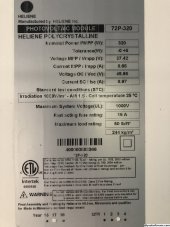
IMG_6105.JPG(solar panel label).
 
if I'm somehow under-sizing my controller...
Don't think l so, with 640 watts of panel, even with , very unlikely, ideal conditions, at a charge voltage of 13.5 volts you have 47 amps. I would be suprised if your system yields more than this, I would expect typically around 40 amps maximum.
The issue you are seeing seems common with Epever solar controllers.
If you want to change to a Victron Controller, a100/50 will work with your panels in parallel. Perhaps a 150/45 for your panels in series, this would also alow future upgrade to 24 or 48 volts ( with more panels for 48v).
 
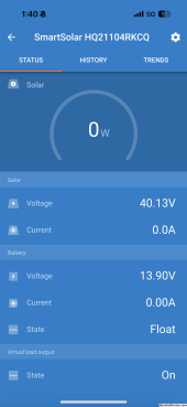
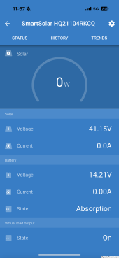
So I purchased a Victron 50 Amp 100V charge controller & seem to still have an over-voltage issue after 2 days of being set up. Solar panels bring in about 140W, the battery voltage jumps to 16.75V, then the Victron shuts off (see video). After disconnecting & reconnecting panels, Victron beeped once. Absorption light is on. Minutes later, it beeped 3 times. Bulk light turns on. Inverter has been off the whole time. I used a multi-meter & the Victron Connect app to check the voltage (40.13V from solar panels & 13.9-14.2V on battery [see pictures]). I have the "Smart Lifepo4" battery setting selected in the Victron Connect app. The app and my multimeter both read 40.13 V from solar panels and 13.9-14.2 V on the battery (multimeter video). I called Renogy to confirm it's functioning properly and all is well. I just contacted Victron support...
 

Attachments

  • 1;40 PM.PNG
    1;40 PM.PNG
    99.8 KB · Views: 2
  • 11;57 AM.PNG
    11;57 AM.PNG
    102.3 KB · Views: 2
The BMS is shutting down the charge path, that's why the display is showing zero current. Go to expert mode in the Victron app and reduce the absorbtion voltage in 0.1 volt steps until you have sucessful charging, ( down to 13.8 volts if necessary). The battery has inbalanced cells, over time things will inprove. What battery do you have, from your comments seems to be Renogy, cell inbalance and unwelcome BMS shutdown seems to be common with this battery.
I guess you are disappointed in not resolving the problem with a new controller, however you now have a controler with better performance and data capture.
Mike
 
Last edited:
Go to expert mode in the Victron app and reduce the absorbtion voltage in 0.1 volt steps until you have sucessful charging, ( down to 13.8 volts if necessary).
I like this but if I were doing this, I would probably start down at 13.8V to get it working at 95% and go up 0.1V as i got greedier (or more knowledgeable or more confident).
 
Just what the other guys have said - your battery BMS is disconnecting the battery and no controller is going to be fast enough to keep the voltage from going too high when it does. SCC depend on the battery being there to take up the charge current. If the battery goes away, up goes your voltage until the over voltage safety kicks in.

Do what Mr Sandals said and set your boost voltage a lot lower so your BMS never disconnects.
 
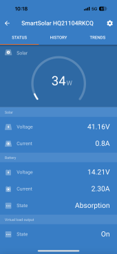
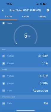
Upon connecting things together, it seems like I have a different issue (see video and pictures). Despite the sunny day, the solar wattage slowly drops. I wonder if I messed something up when I was trying to install a shunt, which happened before this recent screen recording video.

Two silly things happened...
1) I connected the B+ wire for the shunt to the positive battery terminal first and then tried to connect it to the shunt, where I accidentally let the tiny wire touch a component of the shunt. It sparked and then when I properly connected the wire, the shunt/LCD screen failed to operate.
2) The negative wire from the battery-inverter slipped and touched the battery's positive terminal. I connected things and turned on the inverter later (no load), so I don't think a fuse is blown or anything.

Anyway, despite my slip-ups, I definitely have things wired correctly, properly-sized wires, and clean solar panels. I'm wondering if the shunt install failure somehow send power to the Victron & messed it up...
 

Attachments

  • IMG_1686.PNG
    IMG_1686.PNG
    94.2 KB · Views: 3
  • IMG_1691.PNG
    IMG_1691.PNG
    92.7 KB · Views: 3
It sparked and then when I properly connected the wire, the shunt/LCD screen failed to operate.

I'd simplify to try to narrow things down and remove this suspect piece so that you can see if your Victron SCC still works.
Have you looked outside to see if there are any clouds passing by? Or any trees creeping onto the solar panels?
 
Upon connecting things together, it seems like I have a different issue (see video and pictures). Despite the sunny day, the solar wattage slowly drops. I wonder if I messed something up when I was trying to install a shunt, which happened before this recent screen recording video.

Two silly things happened...
1) I connected the B+ wire for the shunt to the positive battery terminal first and then tried to connect it to the shunt, where I accidentally let the tiny wire touch a component of the shunt. It sparked and then when I properly connected the wire, the shunt/LCD screen failed to operate.
2) The negative wire from the battery-inverter slipped and touched the battery's positive terminal. I connected things and turned on the inverter later (no load), so I don't think a fuse is blown or anything.

Anyway, despite my slip-ups, I definitely have things wired correctly, properly-sized wires, and clean solar panels. I'm wondering if the shunt install failure somehow send power to the Victron & messed it up...

I don't see anything wrong here. The SCC has reached absorption at 14.2 volts and the watts begin to taper down as the battery is now full.

If you put a load on your system like turning on something from the inverter, you will see the watts increase again to cover the load.

That's all proper normal behaviour.
 
Back
Top