diy solar

diy solar

Epever Tracer AN series question regarding load terminal

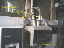
"completing a circuit" meaning check for voltage across the 2 leads going to the LED light?

The 2 pins in the scc take the place of the switch in this circuit. It's nothing more than a switch.

You must apply power to the device you want to turn on and off and use it to control ground or apply power to one side of the pins and use it to switch power.

It does not connect either pin through the scc to the battery.
closed-and-open-circuit.jpg
 
Ok, that was the misunderstanding, I thought I could draw the power from the battery through the SCC and into the light. I didnt realize it was a full relay that needed to be fed on one side and when energized would connect across parallel. So my light should be plugged into the front RIGHT receptacle and my battery power needs to be fed into the front LEFT receptacle, then when the relay is energized it will complete the circuit. That makes much more sense. At present there is no power being fed to the light, so I need to run another set of wires to this port on the controller. This is a bit more than I bargained for, thought it would just pull power from the batteries itself. I will have to get some wire and a fuse then.
 
It's a normally open dry contact.
Sorry i cannot get a pic now, I dont have a cell phone and would have to snap a pic with my camera and process it in the laptop to get it uploaded. But I think I have the idea now, thanks to you both because I have been playing around with this for three days now and getting nowhere.
 
Ok, that was the misunderstanding, I thought I could draw the power from the battery through the SCC and into the light. I didnt realize it was a full relay that needed to be fed on one side and when energized would connect across parallel. So my light should be plugged into the front RIGHT receptacle and my battery power needs to be fed into the front LEFT receptacle, then when the relay is energized it will complete the circuit. That makes much more sense. At present there is no power being fed to the light, so I need to run another set of wires to this port on the controller. This is a bit more than I bargained for, thought it would just pull power from the batteries itself. I will have to get some wire and a fuse then.

You got it!

Their lower models do in fact connect directly to the battery through a contact and even measure the current going out.

These larger controllers do not.
 
Ok, here is a screenshot -
I had the wires from the light connected at "1", I believe I should have them connected at "2" and a separate power feed going into "1"

tracer load port.png
 
Thanks, I would have given up without your help (all of you). Just getting old and not thinking too clearly I guess. I sincerely appreciate the help.
 
Ok, here is a screenshot -
I had the wires from the light connected at "1", I believe I should have them connected at "2" and a separate power feed going into "1"

View attachment 126335
No.
Isn't '1' the Dry relay contact set 1, and #2 is another set of Dry relay contact set #2, same for #3, they are not related to each other.
Each removable Phoenix connector is for a set of relay contact, you have 3 set of relay contacts.
 
Last edited:
Ok, thats where I had the light wired in. Where would the power feed wires go?
There is no power to the number 1 side when the relay is closed (or open). The picture on the decal above those ports seems to indicate a horizontal trajectory to the opposite port.
 
OK, maybe The power goes from one screw on one side the the plug for port 1 to the other screw, as a single line interrupt, like wiring a light switch? Just a break in the positive line? The negative line would go through without interruption?
 
Put a wire to the battery. Attach this wire to upper pin on the left, attach a second wire the pin just below the upper left pin. Attach thus wire to the bulb positive.

Run bulb negative to the battery negative terminal and the light should turn on and off when the load relay is turned on and off.


The pins on the upper right are for sensing battery voltage. Ignore them for now.

Ignorenthem
 
I would suggest to put in-line fuse between battery + terminal and the wire that goes to the terminal, select the correct size fuse so the wire will not burn up if the load draw > current than the wire rating or short circuit.
 
OK, thats what I finally gathered after all your explanations. I do intend on fusing the positive line, just need to research what the specs are on the light. All this looks much clearer in the pictures as the unit is horizontal, but with it fastened tothe wall and surrounded by cabling and other devices (shunt, meters etc) it becomes very hard for me to even see these connections, and its in the basement which is already very dark, hence the light idea. So I am breaking the positive wire at the pins of the left plug, that is the relay. The negative travels through to the light from batt neg. Maybe this will help some others who are in the same situation. Thank you Bud and Chkthis and 12vInst. for this information.
 
Just FYI for anyone else planning on adding things to these ports as they go (yes even the remote battery temperature plug), it is far easier to make all these wiring hookups before mounting the SCC while you can still see the ports. Once mounted all kinds of impediments to reaching these areas...SCC setup.png
 

Attachments

  • light detail.png
    light detail.png
    3.1 MB · Views: 12
Just FYI for anyone else planning on adding things to these ports as they go (yes even the remote battery temperature plug), it is far easier to make all these wiring hookups before mounting the SCC while you can still see the ports. Once mounted all kinds of impediments to reaching these areas...View attachment 126409

The parts with the little flathead screws unplugs from the charge controller. You can unplug it, connect the wires to it and then plug it back into the controller.

s-l1600.jpg
 
connect the wires to it and then plug it back into the controller.
…and then support the wires so the little connector isn’t bearing weight.

After having a 50A Epever come with a stripped charge-out/battery cable terminal screw and then waiting too long to return- not a problem- and discovering NO parts are available- that IS a problem) I’m in kid glove mode with Epever now. Great controllers, but no parts is the third ‘thing’ that is dubious with them. Epever is like 97% of being fantastic.
(The other two being the high-voltage spike shutdown glitch (software bug along with slow processing of high voltage variances from the solar panels) while charging lead acid, mostly) and that I (and not most but many others) could not get settings to save/stick with the MT50- thankfully the PC app works well.)
 
With the breaker open it gives continuity between batt(-) and load(-) but no continuity on pos(+).
The "N" on the AN, BN etc series designate them as "Negative Common" (positive switched), so the negative terminals are always tied together.

The typical non-MPPT SCC is 'positive common' (negative switched).
 
Back
Top