diy solar

diy solar

Exactly HOW does the BMS Stop the Charging Process?

bass-o-matic

New Member
Joined
Oct 26, 2023
Messages
62
Location
Austin, Texas
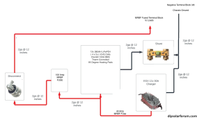
See this basic setup.

How exactly does the BMS stop the charging process? It's not connected to the charger. Did I miss a component?
How does it tell the charger to stop?
Is it able to tell the cells to stop accepting charge?

Keep in mind my RV will be just sitting plugged in to shore power 95% of the year.

Thanks for an input.

BMSHowTo.png
 
How exactly does the BMS stop the charging process?

It doesn't tell the charger. It blocks the current path to the battery in either charging or discharging direction (or both). If you want to know the details:

 
A lot of effort is made to get the charger to stop in time, through voltage settings and comms, same with the load.

When that fails the BMS cuts off the power by FETs or by Contactors. They are a last resort, a safety switch. Your BMS has built in FETs. FETs have a magic ability to reverse current in one direction, they can, in one wire, cut off flow in one direction and allow it in the other.

But really all of us are trying to design systems that won't fall back to the FETs or Contactors to stop the charge or load.

It's the solar world that puts a lot of the brains in the inverter and tries to make it the master, receiving info from the BMS to enable it to make the right decisions. In the EV world the BMS gets a lot more direct responsibility and it is the one telling both the load and the charger what to do so that it doesn't have to cut them off by the contactors.

In your design without comms, it is the charger that is using voltage settings to back off before it has to be cut off. Normally, when balanced, the top voltage that charger will raise the bank to is not so high that it will have to be cut off. The battery is capable of rising to and meeting that voltage.

Maybe the concept to grasp is voltage current interaction. If the charger is at a voltage, and the battery is at the same voltage, the charger cannot push any more current into the battery due to the laws of electromagnetism. The charger does not have to make an intelligent decision to pull back the amperage when voltages meet, it physically cannot push any more amps into a battery at the same voltage as it.
 
Last edited:
The charger does not have to make the decision to pull back the amperage when voltages meet, it physically cannot push any more amps into a battery at the same voltage as it.

Which is also when your charger can go into float mode, i.e., a lower voltage so the cells in the battery can settle. For LFP, ideally, you even don't need a float mode, but typically it's at 3.375V or so.
 
Thank you! I think I get it.

So in my design it's really up to the charger to stop the charge. My EG4, although rated for LiFEPO4, is not programmable from what I can tell and so I can't tell it to stop at 90% SOC. But it will float at that point... or is smart enough to back off.

I can however, program my Epever Charge Controller to stop at 90% ... I believe. It's not on the schematic. I wanted to keep it simple.

Did I get it?
 
I'm curious what your shunt is intended to do in that diagram, or what it is connected to. Does the overkill BMS read the shunt?
 
My EG4, although rated for LiFEPO4, is not programmable from what I can tell and so I can't tell it to stop at 90% SOC. Unless that's built into it somehow?
Correct. Your EG4 has predefined voltage settings that cannot be changed and it will charge to 100% unless something stops it. And nothing in your diagram will stop it. Unless the battery is unbalanced and the BMS reaches it's safety cutoff due to an individual cell voltage rising too high.
 
Which is also when your charger can go into float mode, i.e., a lower voltage so the cells in the battery can settle. For LFP, ideally, you even don't need a float mode, but typically it's at 3.375V or so.
It's something I need to learn more about, to understand why they still choose to build a float backoff into LFP chargers. Is it because the higher voltage absorption achieves a faster charging time? Cause it seems safer and gentler in my mind to just CV/CC all the way to a single target. Why have this risky middle stage voltage push.
 
It's something I need to learn more about, to understand why they still choose to build a float backoff into LFP chargers. Is it because the higher voltage absorption achieves a faster charging time? Cause it seems safer and gentler in my mind to just constant current to a single target.

The main reason is to make sure the SCC keeps powering loads, without micro-cycling the battery. Higher voltage absorption is especially crucial for those that have a limited time window in which to charge their batteries. However, you still want the cells to settle and even keeping them at 3.45V for prolonged periods (i.e., more than needed to absorb) can lead to overcharging. At 3.375V, you shouldn't be able to overcharge at all, so it's a safe voltage to be at even if the battery is fully charged.
 
Does the overkill BMS read the shunt?
No. My Overkill BMS is relatively dumb.

In my experience you either have:-

a) a basic system, as shown above where there is no feedback from the BMS or Shunt to tell the charger what to do. The charger will just charge to the voltage it is designed to do, either dumbly, or having some in-built charge profile using its own voltage and/or current measurements.

or

b) You have an inverter (or charger) that receives data from the BMS that tells the inverter or charger what to do. Typically this data is communicated over CANBus or Modbus over an RS485 connection. In that case, the BMS (or control system attached to the BMS) will tell the inverter what the SOC is, what max current to charge at, what max voltage to use and what max current to discharge at.
 
I'm curious what your shunt is intended to do in that diagram, or what it is connected to. Does the overkill BMS read the shunt?
Just goes to a Camway Battery Monitor. My underrating is it measure power going in... power going out.

a) a basic system, as shown above where there is no feedback from the BMS or Shunt to tell the charger what to do. The charger will just charge to the voltage it is designed to do, either dumbly, or having some in-built charge profile using its own voltage and/or current measurements.
BINGO! That was my next question. In my setup what DOES the BMS actually do? Is it able to balance the cells when charging? I see that as a setting. But I have no idea how it does that with those little wires...

So, some lights are coming on here...

1. If the BMS in my setup detects an issue, too hot, too cold, overcharge, etc. All it can do it open the ground circuit and thus cut off power to my trailer? I guess I would like to confirm that behavior.

2. It's really up to the EG4 Charger to not overcharge or undercharge the batts.

3. I'm looking at my EG4 manual. I don't see any information other than it charges to 100%. Still digging... I would think it would be designed to only go to 90% SOC and then.... float? Maybe I'm overthinking this one.

I think where I'm going is... How important is it that I have power below freezing? When am I ever going to be in my trailer when it's below freezing? Probably NEVER. If that were a concern... I would want a BMS that can shut off the CHARGER... and not just open the ground/kill the power so I would still have lights. Meh.

And, I should just trust the EG4 to charge properly. The Float probably keeps it at 90% SOC and it's not going to be doing 3.65 per cell all the time.

Hmmmm.... I've gone down a rabbit hole but perhaps needlessly.
 
Last edited:
Correct. Your EG4 has predefined voltage settings that cannot be changed and it will charge to 100% unless something stops it. And nothing in your diagram will stop it. Unless the battery is unbalanced and the BMS reaches it's safety cutoff due to an individual cell voltage rising too high.
How much should this bother me?
 
How much should this bother me?
None, if what you want it to do is charge your batteries to 100%. Afaik EG4 chargers like that charge to 3.65 per cell.

If one decides that they don't want to charge to 3.65v per cell. Then it's a problem, since it cannot be changed.
 
1. If the BMS in my setup detects an issue, too hot, too cold, overcharge, etc. All it can do it open the ground circuit and thus cut off power to my trailer? I guess I would like to confirm that behavior.

It will do so with a somewhat finer granularity. For example, if it drops below a certain temperature, charging can be disabled, but discharging can remain enabled. It's not a straight everything or nothing (see that MOSFET thing I linked to before).

2. It's really up to the EG4 Charger to not overcharge or undercharge the batts.

Yes, and the BMS is the protection device if something goes wrong to prevent damage.

3. I'm looking at my EG4 manual. I don't see any information other than it charges to 100%. Still digging... I would think it would be designed to only go to 90% SOC and then.... float? Maybe I'm overthinking this one.

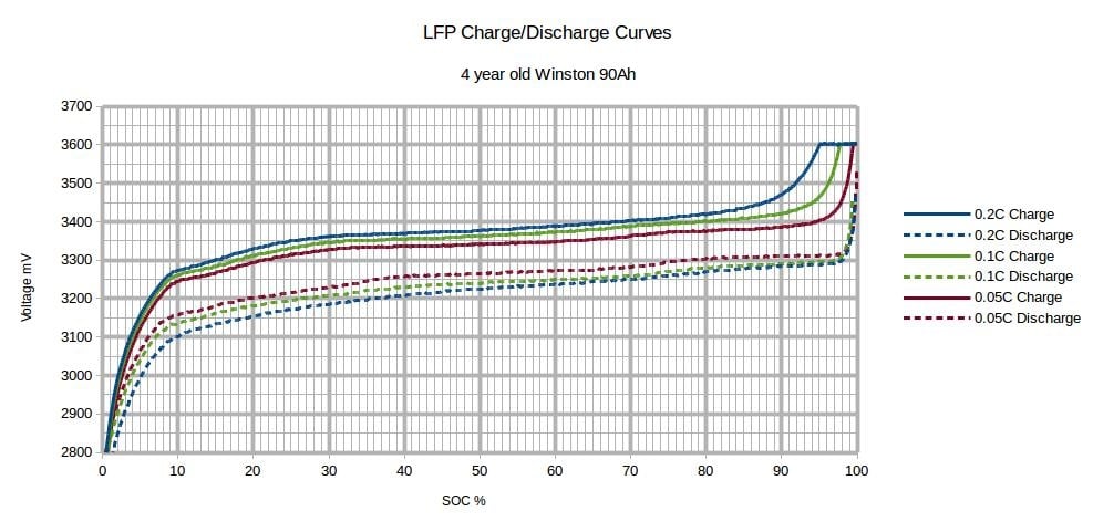
You can only determine 90% SoC on LFP with a shunt (Coulomb counting), since voltage is not an indicator except in the knees:

qidwvcdb3z4i.jpg
 
1. If the BMS in my setup detects an issue, too hot, too cold, overcharge, etc. All it can do it open the ground circuit and thus cut off power to my trailer? I guess I would like to confirm that behavior.

2. It's really up to the EG4 Charger to not overcharge or undercharge the batts.

3. I'm looking at my EG4 manual. I don't see any information other than it charges to 100%. Still digging... I would think it would be designed to only go to 90% SOC and then.... float? Maybe I'm overthinking this one.
1. Yes but it can cut off in one direction. It can decide it's too cold for charge but not too cold for discharge, and only allow discharge.

2. Yes, but the BMS still acts as the policeman, if it thinks the EG4 is overcharging it can cut it off.

3. It will charge to 100%, it is designed to hold at 100%, not 90%.
 
Yes, the BMS has FETs and they act like a reversible diode. They can allow power flow in both directions, or only one direction, in either direction
Sweet! That is the concept I was missing.... diodes. I have limited understanding of circuits, Open, Closed, Diodes are like one way things, Transistors are switches/valves, resisters resist, thermistors... Ok I know some stuff but now all the theory.

Soooo.... in my configuration... the only real issue is... that the charger is going to go to 100% and oh, wait... no... the BMS can stop the flow in charge mode at 90% because... it's a DIODE! Right?

And it's saying, "Electrons! You can only flow in the discharge direction! Not the charge direction!"
 
Sweet! That is the concept I was missing.... diodes. I have limited understanding of circuits, Open, Closed, Diodes are like one way things, Transistors are switches/valves, resisters resist, thermistors... Ok I know some stuff but now all the theory.

Soooo.... in my configuration... the only real issue is... that the charger is going to go to 100% and oh, wait... no... the BMS can stop the flow in charge mode at 90% because... it's a DIODE! Right?

No, it won't know 90%. It doesn't have a switch for that, it only knows voltage, and voltage isn't a state of charge. Also, the BMS should not be relied on in normal operations, only as a protection device.
 
Back
Top