diy solar

diy solar

Excess solar for EV charging - how to automate?

Hence my proposed plan--above--to have a second smart loads breaker panel and have the Vue monitor that.
That could work but you would have to fool the Vue by placing the CTs on the solar production like I do and the EVSE adjusts based on solar production. The Grid sensors of the Emporia would have to be on that panel but then the Emporia data would be useless for overall system data.
 
Where are you suggesting the "external CTs" would go?
I would have to see a system diagram to know details. The concept was to put the external SolArk CTs at the main panel and have the EVSE be powered in such a way that it is a load that the CTs see and do not curtail. The problem would be placing Emporia Grid CTs at same spot so the Emporia would reduce current. Otherwise the Emporia would not reduce current and draw from grid.
That is what I did years ago but had to constantly manually change current so as to not draw from grid. @zanydroid has some suggestions that might be simpler.
 
Last edited:
Thanks for all the responses so far.

It is good to hear the Emporia “excess solar” mode works on their charger together with their Vue energy monitor. Really smart strategy on their part to build a system this way. However, I don’t think it will work for our situation. As I understand it so far, the Vue uses current sensors on the mains so their “excess solar” mode is essentially doing zero metering. It ramps the charger down and up trying to get the outbound power towards zero. Cool. But.

Unfortunately our Sol-Ark is going to be doing the same thing as the Emporia system because we need to operate it in zero meter mode as we can’t export power to the grid, so it would be decreasing output power to the house regardless of excess solar. This means the Vue is never going to see negative power (export) so it won’t ramp up the EV charger, so the car always gets nothing. At least this is how I understand the Emporia solution.

The Sol-Ark 15k and EG2 18KWPV have a “smart load” function (replacing the auto generator mode, as mentioned above by Ampster & Rusty959). This is binary on-off based on programmable thresholds on PV and battery SOC, so it won’t work to provide variable power the EV charger. So what about this idea? What if I connected these smart load terminals to a water heater element in a pre-heat tank AND to the EV charger. Let the Emporia Vue measure current for just the water heater. The Emporia algorithm would then regulate the EV charger trying to consume the “extra” power going to the water. The Central controller would regulate the smart load on or off when there is excess solar so when the sun goes down the EV charger would not pull from battery. When the car is full or unplugged the charger would direct all the excess solar into the water. Neat. The only glitch would be when the water tank hits its high temp limit shutting off it’s heater element. When this current went to zero I think Emporia would ramp the EV charger down to zero thinking there was no excess solar. I would have to use a larger tank or come up with another energy sink like sending the water to a hot tub in the summer or to a water-to-air radiator in the winter but that would be a good thing. And I would need a “car priority” transfer switch to power the EV charger from mains when the car needs charging when there is no excess solar.

Another crazy idea would be to power charger from mains and use an IotaWatt to measure PV and battery, and some custom software to command the appropriate charge current on an OpenEVSE charger. This custom software could then also charge the car when the PV goes to zero indicating it is night time and there will be no excess solar coming before the car needs to be full by morning for tomorrow's commute. If we ever get TOD or surge pricing here we could incorporate timing and power limiting into this special software to optimize for lowest cost. I know also nothing about IotaWatt or OpenEVSE programming, other than they are both open source, so I’m just guessing this is possible at this point.
Are you really losing so much excess solar energy that there is a real problem/need? Your idea sounds pretty complex and likely not cheap in terms of time and/or money to implement. So, I wonder if it's a serious pursuit.
 
Are you willing and able to program a Raspberry Pi?

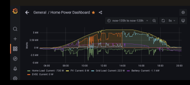
I'm running an Open EVSE, sucking up any PV the car can take while plugged in. It works great. But, I'm grid tied, so it isn't quite the same.
Yellow is PV, orange is the EVSE.
Screenshot_20230505-201453.png

All you'd need to do is pole PV watts from the Solar, subtract home loads, and send that the the EVSE once the battery hits 95% or something similar.

Your water heater/current sensor combo won't work. Electricity will go everywhere in the circuit, you aren't going to pull current away from the water heater.

If you don't want to/can't program something to do the math and send the commands, another option is to just set the EVSE to charge at your afternoon PV production and let the SolArk cycle the gen port on at 95% and off at 90%
If the EVSE is set to charge at 4kW and you have 6kW of PV and 800 watts of home load, it would be close enough. So what if the sun goes down some and you pull a couple kWh from the battery? Just don't let the car charge at full speed.
 
I wonder if you can just detect when the battery is essentially full, and use this to trip a relay.

This relay could trip an on / off to allow charging - at least in theory.

If the pack voltage / SOC drops too low, then flip the relay off.

That way it could just run from the main power system.

A simple PLC might work.
 
Thanks for all the responses so far.

It is good to hear the Emporia “excess solar” mode works on their charger together with their Vue energy monitor. Really smart strategy on their part to build a system this way. However, I don’t think it will work for our situation. As I understand it so far, the Vue uses current sensors on the mains so their “excess solar” mode is essentially doing zero metering. It ramps the charger down and up trying to get the outbound power towards zero. Cool. But.

Unfortunately our Sol-Ark is going to be doing the same thing as the Emporia system because we need to operate it in zero meter mode as we can’t export power to the grid, so it would be decreasing output power to the house regardless of excess solar. This means the Vue is never going to see negative power (export) so it won’t ramp up the EV charger, so the car always gets nothing. At least this is how I understand the Emporia solution.

The Sol-Ark 15k and EG2 18KWPV have a “smart load” function (replacing the auto generator mode, as mentioned above by Ampster & Rusty959). This is binary on-off based on programmable thresholds on PV and battery SOC, so it won’t work to provide variable power the EV charger. So what about this idea? What if I connected these smart load terminals to a water heater element in a pre-heat tank AND to the EV charger. Let the Emporia Vue measure current for just the water heater. The Emporia algorithm would then regulate the EV charger trying to consume the “extra” power going to the water. The Central controller would regulate the smart load on or off when there is excess solar so when the sun goes down the EV charger would not pull from battery. When the car is full or unplugged the charger would direct all the excess solar into the water. Neat. The only glitch would be when the water tank hits its high temp limit shutting off it’s heater element. When this current went to zero I think Emporia would ramp the EV charger down to zero thinking there was no excess solar. I would have to use a larger tank or come up with another energy sink like sending the water to a hot tub in the summer or to a water-to-air radiator in the winter but that would be a good thing. And I would need a “car priority” transfer switch to power the EV charger from mains when the car needs charging when there is no excess solar.

Another crazy idea would be to power charger from mains and use an IotaWatt to measure PV and battery, and some custom software to command the appropriate charge current on an OpenEVSE charger. This custom software could then also charge the car when the PV goes to zero indicating it is night time and there will be no excess solar coming before the car needs to be full by morning for tomorrow's commute. If we ever get TOD or surge pricing here we could incorporate timing and power limiting into this special software to optimize for lowest cost. I know also nothing about IotaWatt or OpenEVSE programming, other than they are both open source, so I’m just guessing this is possible at this point.
I don't think your the Vue on the water heater element would work like you're hoping. The Emporia system turning up the charger wouldn't be decreasing power to the water heater, so it would just continue to ramp up to max power. No different than if the Vue wasn't there at all. I do agree your no export settings make this harder.

Maybe try looking into the peak management feature with the main CTs connected at the meter as typical? I think if you connected the Emporia charger to the smart load port and then set peak management to something stupid low like 50 watts it would turn down the charger to meet that peak demand limit, or it would be off when there's no chance of excess solar.
Biggest flaw I see on this is you may have to have the peak management value set to a higher number than the step resolution of the EV charger, which I don't know. I bet it's 1 amp, which means you may need a 250+ watt min peak? That being said, at worst you'd be *slightly* charging from the grid, but the bulk would be excess solar.
 
I wonder if you can just detect when the battery is essentially full, and use this to trip a relay.

This relay could trip an on / off to allow charging - at least in theory.

If the pack voltage / SOC drops too low, then flip the relay off.

That way it could just run from the main power system.

A simple PLC might work.
What you're describing is very similar to the smart load feature on the Sol Ark 15k or EG4 18kpv
 
Oh, maybe an easy idea to make the Emporia work. But also dumb, risky, and still a little complex.

I still prefer programming a Raspberry Pi or PLC.

But, you could take the emporia, put the grid current transformers on the DC batter cables. The emporia would crank up the charge current until the PV was going to the home loads and charger.

But, this still requires the SolArk to turn on the smart load, gen, whatever to power the EVSE after the battery is charged but before it has started curtailing PV production.

It also relies on Emporia going through simple route when the are figuring out the available EVSe current. You'd need it to work incrementally, where it turns on the EVSE to some minimum, looks at the "grid current" (in this case battery current) and decide if there is still enough excess current to make the next step up with the EVSE.

Also, it may require swapping out the type of current sensor for a different type. Plus you've got to hope the Emporia doesn't do a dumb because the current is DC, not AC.
The methodology of measuring DC current with a "clamp" is different enough from AC that I think your Raspberry Pi option would be far easier than tricking the Vue into reading a DC current.
Interesting idea though, fundamentally I think it could work with enough tinkering. You're basically just looking at the batteries as a grid. And on that note, you could possibly get it to work with the right AC coupled setup with the standard Vue. But a lot of speculating here.

I've been considering the Emporia EV charger for so long I probably just need to buy it and answer some of these questions myself, even though I have net metering.
 
Im not familiar with the Vue system but excepting that obvious hole in my
knowledge im not aware of a system that automates this desire. I think to do it ‘well’ would require taking control of the EVSE communication signals to vary the ‘current limit’ based on the rest of your homebrew system, and to measure your available power directly rather than rely on a signal from an existing inverter. I would measure charging current to battery as the reference because charging current will only exist after other AC loads have been met. Since you know battery voltage range within a narrow window its pretty easy to correlate battery amps to excess watts available so that the EVSE doesn’t overshoot the target. But at the end of the day you WILL be programming things to accomplish it and unfortunately i dont know a damn thing about that which will be the bulk of the ‘work’. ?
 
You can really get wrapped around the axel trying all these options or just use Emporia and a Net Meter. You said you are connected to the grid already.
 
You can really get wrapped around the axel trying all these options or just use Emporia and a Net Meter. You said you are connected to the grid already.
But the Emporia relies on grid export to control EVSE current. The OP is on a zero export set up, so the Emporia (or similar systems like Open Energy Monitor/OpenEVSE) won't work as there is never export to measure and divert to the EVSE.
 
But the Emporia relies on grid export to control EVSE current. The OP is on a zero export set up, so the Emporia (or similar systems like Open Energy Monitor/OpenEVSE) won't work as there is never export to measure and divert to the EVSE.
No, but you can fake it with math.
 
But the Emporia relies on grid export to control EVSE current. The OP is on a zero export set up, so the Emporia (or similar systems like Open Energy Monitor/OpenEVSE) won't work as there is never export to measure and divert to the EVSE.
No it relies on what it perceives as the difference between solar produced and total consumption and that depends on where you place the CTs. Normally one would place the main CT at the meter and your statement would be correct. However, it could be placed somewhere before that point. But then the Emporia would not be useful for other purposes. The EVSE would have to be situated such that the load would count as load before the limiter on the inverter would curtail. I think @Shimmy is saying something similar.
 
But the Emporia relies on grid export to control EVSE current. The OP is on a zero export set up, so the Emporia (or similar systems like Open Energy Monitor/OpenEVSE) won't work as there is never export to measure and divert to the EVSE.
The "zero export" works the same way as the Vue, it still has to have a CT to know when to stop sending out to the grid.
 
No, but you can fake it with math.
That was my suggestion, see post 26. You've got to pull the numbers for the math from somewhere.

No it relies on what it perceives as the difference between solar produced and total consumption and that depends on where you place the CTs. Normally one would place the main CT at the meter and your statement would be correct. However, it could be placed somewhere before that point. But then the Emporia would not be useful for other purposes. The EVSE would have to be situated such that the load would count as load before the limiter on the inverter would curtail. I think @Shimmy is saying something similar.
Where are you proposing to put the CTs? None of the options I see would make it work: Inverter output to loads, inverter input (from grid or to not backed up loads), PV (but that is DC)

The "zero export" works the same way as the Vue, it still has to have a CT to know when to stop sending out to the grid.
You can't have two pairs of CTs on the same spot (grid connection) with each system fighting for the zero point in zero export and have it work well. Plus the EVSE has a minimum current of 6 amps and 1 amp steps, so it would loose and you'd never charge, the SolArk would continue to run zero export as usual.
 
For whatever reason this is stuck on my mind. Another idea I've got is I bet you can make a pretty simple circuit that would just shift the reading of the CT for the emporia however much you wanted. If you set it so when the smart load is active you also shift the emporia's reading by a few hundred watts it would do what you need it to do.

I've got an extra emporia vue laying around, I really just need to try it.
 
That was my suggestion, see post 26. You've got to pull the numbers for the math from somewhere.


Where are you proposing to put the CTs? None of the options I see would make it work: Inverter output to loads, inverter input (from grid or to not backed up loads), PV (but that is DC)


You can't have two pairs of CTs on the same spot (grid connection) with each system fighting for the zero point in zero export and have it work well. Plus the EVSE has a minimum current of 6 amps and 1 amp steps, so it would loose and you'd never charge, the SolArk would continue to run zero export as usual.
You put the CTs for the Solarark on the line, you put the CTs for the Vue at the meter.

This is how I have it right now. :)
 
Back
Top