Folks
I am putting in a multiplus-II in my fifth wheel.
I am using the Lynx 1000 Shunt and Lynx 1000 Distributor
I will be starting with two connections to the Distributor, one for the mulitpluss and one for the trailer loads
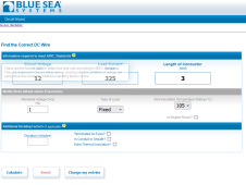
The mulitpluss fuse on the distributor works out to 325 amps based on a max continuous current of 255
It is not completely clear, but I am guestimating that the coach loads would work out to fifty to 75ish max
The current coach loads pull on a 6 gauge wire.
So check my guess work.
The awning, Leveling Jacks, and slide motors are all protected by a common 30 amp shortstop automotive type thermal breaker
The tank heater is protected by a 30 amp shortstop breaker.
The coach wiring (led lights, furnace, fans etc) are protected by a 50 am shortstop automotive breaker.
The only long term continuous load I could see, would be the tank heaters and the coach at say 50%. Everything else is intermittent.
I have four 200ah batteries in parallel
So my fuse plan would be
Lynx-distributor to/from multiplus: 325 amps
Lynx-distributor to/from trailer buss: 75 amps
Lynx Shunt: 400 amps (too high?)
Wiring Plan:
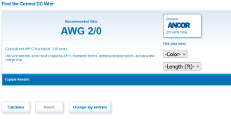
Lynx Distributor to/from multiplus: 2/0 (Peak current is 250, so this seems slightly undersizesd but it is what Will used)
Lynx Distributor to /from trailer buss: AWG 6 ( that is what the current system uses, so going to call it OK)
Lynx Shunt to / from battery bank: 4/0?
Battery to battery interconnects: 2/0
Some how this seems like the fuses are higher rated than the cabling?
Am I missing something?
Thanks
ANdy


