diy solar

diy solar

Growatt 12k passthrough

Filterguy and I have talked extensively, and I feel safe with the wiring diagram he recommended. Filterguy did say that if I posted the wiring diagram online to expect some backlash, so it was not posted publicly.

For what it is worth, the shop system with the growatt 6k, is now connected to the grid. It does switch over to grid bypass when the batteries reach ~30%soc and back to pv/battery power when soc reaches ~50% without issue.

ONe thing that concerns me in regards to sigsolar stating " ... The inverter has a current sensor on each leg for the protection. ... ", in regards to internal transformer protection when bypassing grid power, is that when the growatt 6k is bypassing grid to the shop, Solar Assistant does not report any usage of grid power. So yeah, I'm not so sure the growatt has any ct sensors monitoring grid bypass current.
I've noticed that in Solar Assistant as well. It only records like 40-60 watts trickling into the battery when in passthrough mode. If you set it to utility charging, it notes whatever you set the utility charging amperage to. I wish it would say what the draw was in grid mode since that would be pretty useful information. I get your concern about whether that's a deficiency in the growatt itself or a missing feature in the SA software. You want to think these things are designed with all contingencies in mine but you never know.

I'd be interested to see your wiring diagram if you're willing to share it.
 
Last edited:
check out the video at 29:30. There you can see the output of the transformer being connected next to the current sensors so I suppose what they're saying is correct.

 
The question asked at the bottom of post#330 "Does the Growatt spf6000tdvm have any internal safety measures to insure its internal transformer does not become overloaded from passing neutral to the grid.".

So yeah, I had an uneasy feeling about the overly vague answer provided by growatt/SigSolar and really hoping they were referring to the unit having internal current sensors, which is what that the conversation was centered around, for transformer overload protection. Breakers ... am I wrong in thinking they are not going to add much protection from neutral overload of the tranny?
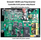
There appears to be a transformer core temperature sensor going from its core to lower left hand corner of control board. This is a pretty important requirement to have.

There are two CT transformers on upper right-hand side of control board on L1 and L2 legs of transformer secondary. Difference in AC current between L1 and L2 sides of transformer would be transformer neutral current.

In the video I cannot see where transformer neutral is connected. I am guessing it goes directly from transformer to AC external terminal strip and was not disconnected in the disassembly video. This also means the inverter controller has no knowledge of L1-N or L2-N voltage.

I don't see another set of CT transformers for AC input lines??? This is usually necessary to tell how much AC output load current is coming from AC pass-through, and by adding or subtracting any AC current going to inverter transformer. Knowing AC input current is also necessary to do any AC input load shaving with inverter supplementation.

I also do not see any small AC voltage step down transformers on control board to supply electrically isolated, lower voltage AC representation to microcontroller for AC voltage measurements on AC input and inverter AC output voltages. Hopefully they are not just using a series coupling capacitor and voltage divider resistors for this. That method would be risky for microcontroller survival when lightning hits utility power lines.

On a LF inverter, battery charging current from AC input can be calculated from AC current into transformer, along with AC voltage, and a fudge factor for inverter loss at a given transformer load power. This eliminates need for a high current shunt in battery lead which is extra expense and difficult with its high current connections. My 25-year-old Trace inverters do it this way.

With PV charge controller output going directly to battery terminals on inverter, the PV charge controller must be controlling it output current as an independent path. Inverter controller must know how much battery charge current is coming from PV source and how much is coming from inverter AC input in order to control total net battery charge current.
 
Last edited:
There appears to be a transformer core temperature sensor going from its core to lower left hand corner of control board. This is a pretty important requirement to have.

There are two CT transformers on upper right-hand side of control board on L1 and L2 legs of transformer secondary. Difference in AC current between L1 and L2 sides of transformer would be transformer neutral current.

In the video I cannot see where transformer neutral is connected. I am guessing it goes directly from transformer to AC external terminal strip and was not disconnected in the disassembly video. This also means the inverter controller has no knowledge of L1-N or L2-N voltage.

I don't see another set of CT transformers for AC input lines??? This is usually necessary to tell how much AC output load current is coming from AC pass-through, and by adding or subtracting any AC current going to inverter transformer. Knowing AC input current is also necessary to do any AC input load shaving with inverter supplementation.

I also do not see any small AC voltage step down transformers on control board to supply electrically isolated, lower voltage AC representation to microcontroller for AC voltage measurements on AC input and inverter AC output voltages. Hopefully they are not just using a series coupling capacitor and voltage divider resistors for this. That method would be risky for microcontroller survival when lightning hits utility power lines.

On a LF inverter, battery charging current from AC input can be calculated from AC current into transformer, along with AC voltage, and a fudge factor for inverter loss at a given transformer load power. This eliminates need for a high current shunt in battery lead which is extra expense and difficult with its high current connections. My 25-year-old Trace inverters do it this way.

With PV charge controller output going directly to battery terminals on inverter, the PV charge controller must be controlling it output current as an independent path. Inverter controller must know how much battery charge current is coming from PV source and how much is coming from inverter AC input in order to control total net battery charge current.
Wonder why there are no measurements with Solar Assistant when the GW is bypassing grid?

Other than lightning, do you feel the GW 6k has overall sufficient protection, and what if it is forced to deal with an overly unbalanced utility transformer?
 
I have re-read this entire thread a few times to gain understanding

I have looked at Growatt 12kw for my system as a lower cost inverter than the Sigineer 15kw inverter.

I use Tesla Model S battery modules (protected by the ESP32 battery controller, which utilizes Tesla's own BMS boards on each module) and the Growatt's charging parameters wastes a lot of battery capacity, LVD at 40v or 42v, while Tesla goes down to 36 or 38v. Currently my bank is at 50kwh.

So I again looked at the Sigineer 15kw that has proper Tesla charging profile, to look at their handling of the N-G Bonding issue

Well, I found that Growatt 12kw is basically a Sigineer with better User Interface. The Growatt uses the Sigineer transformer and other base parts, then researching more on Sigineer, I found some answers on N-G Bonding, etc at SigineerPower website

For what it is worth, here are those links

120V / 240V Split Phase Inverter Chargers​


Schematic


Important wiring instruction for split phase inverter chargers with floating neutral​


Link to my build thread post, where I documented the above as well
I have installed a 3 pole double throw transfer switch (for L1, L2 and Neutral) to allow switch my critical loads panel between grid and inverter output


still searching for my Truth...............(lol)
 
Last edited:
For the record, I am not 100% convinced the unit has any kind of internal transformer overload protection device in service, other than a circuit breaker.
 
Last edited:
Schematic has several errors. You would not ground HOT 2 leg. What is labeled as Main Relay 02 is pass-through relay for L2 input side.

They appear to put two 40A relays in parallel on each L1 and L2 lines in attempt to achieve 80 amp pass-through current. They don't actually spec pass-through current, but their AC input hookup recommends an 80A AC input breaker.

Other Chinese manufacturers do the same thing to handle greater pass through current and it is bad engineering practice since the parallel relays will not share current equally or, more importantly, open and close their contacts at the same instant in time.

What has got me curious is why they have two different manufacturers for the 40 amp relays (see picture).

There appears to be no relay to ground neutral to output transformer center tap when there is no AC input.

There also appears there are two CT transformers on L1 and L2 legs of inverter output transformer. This is necessary to measure 120vac load imbalance current. Curious thing is their placement might mean they are also pulling double duty to provide PWM filtering inductance. It would be easy to filter the CT transformer secondary to remove higher frequency PWM waveform remanence from CT sensor output.

Growatt appears to do no measurement on pass-through AC input current. It detects grid collapse from inverter overload surge current causing pass-through relays to open to grid. This is the common way for LF inverters to detect grid collapse.

You need additional CT sensors on AC input L1 and L2 lines to provide load shaving capability which Growatt does not have. I have no idea how they prevent pushing power to grid without AC input current sensors, unless they are just measuring AC voltage drop from AC input to AC output to indicate current is always only flowing from AC input to AC output.

Speaking of AC voltage measurement, I see no low voltage isolation AC voltage sensor transformers. It would need two for each 120vac phase. They must be just using a resistor divider network which is bad for controller processor isolation from AC mains. That is what appears above the green AC input filter capacitor on left of picture. Hopefully the little 4 pin IC U11 is an opto-isolator.

They appear to modify PV SCC setting to regulate battery charging based on how much AC current is going into inverter transformer to adjust supplementing battery charging in parallel with PV charging. It is common for LF inverters to regulate battery charging via AC input current to inverter with AC input power to DC output power calculation, with a fudge factor for inverter losses.
12k control board 2.png
 
Last edited:
Thank you everyone for this informative thread. I wish it didn’t come to the conclusion it did (ruined my plans…), but safety is important!

However, I wanted to follow up on two things. First, to paint a picture of what I’m dealing with…

I have an off grid 12K that looks almost exactly like the diagram below (WITHOUT the Input AC connection). Solar shed powers four RV power pedestals (with three RVs typically hooked up). G-N bond is in the shed panel, grounded to earth with a ground plate.
1665201174890.png
My hope was to have a glorified extension cord running from the nearby cabin to the Growatt to enable AC battery charging for those winter days (multiple resistive heaters and less sun) as a backup - I didn’t realize until diving in that it doesn’t just charge but actually bypasses and charges while in bypass mode. I guess I should have read more when I was purchasing. My original plan was to have a 240V extension cord with two hots and a ground similar to the above photo, not including neutral. Then I got concerned how the neutral was going to work in bypass mode when I found that it had no charge-only option.

1) Can you ELI5 why the above diagram (with a ground added, which itself would be G-N bonded at the panel in the house) doesn’t work to a non-electrician that dabbles with the key focus of not dying?

2) An isolating transformer was mentioned as a potential solution. Can anyone point me in the direction of an available product that might allow this to function safely? I assume it is expensive, but I just wanted to have all the options in front of me.

Bonus Question) I’m currently leaning to just stay off-grid from an AC connection to avoid the issue altogether. In order to have a backup from the grid-world, I could just run a grid-AC-powered 48V charger - potentially even with a relay trigger to turn on and off with the dry contacts on the inverter (or the BMV-712 I have on the battery bank). Anybody have a good suggestion, as they are expensive too? I have 15A 120V and 30A 240V accessible from grid, and currently have no separate 48V battery charger.

Thank you all for keeping us safe with the deep dive into poorly-documented inverters.
 
Thank you everyone for this informative thread. I wish it didn’t come to the conclusion it did (ruined my plans…), but safety is important!

However, I wanted to follow up on two things. First, to paint a picture of what I’m dealing with…

I have an off grid 12K that looks almost exactly like the diagram below (WITHOUT the Input AC connection). Solar shed powers four RV power pedestals (with three RVs typically hooked up). G-N bond is in the shed panel, grounded to earth with a ground plate.
View attachment 115499
Here is the issue with Growatt LF inverter connected to grid. (same for AIMS, and others similar inverters)

Because they lack management of grid neutral imbalance it is risky to connect grid neutral to AC output neutral. With grid neutral connected to output transformer neutral, the output transformer secondary windings act like an autotransformer and output transformer will try to correct any grid neutral imbalance. The only apparent safety for this is an inverter shutdown for an overheating output transformer. Long before the time it takes for the transformer to heat up, the output transformer can be limited on additional inverter functional power handling so it can approach saturation causing MOSFET current to rise to destructive levels.

Without the grid neutral connected to AC output neutral there will be high vulnerability from lightning strikes blowing out the inverter. This is due to your independent AC output ground being isolated from grid system ground. When lightning strikes there can be thousands of volts difference between your ground and grid ground, with grid AC input L1-L2 following grid ground reference.

LF hybrid inverters like Xantrex and Outback monitor grid neutral current imbalance, with AC input current monitoring, as a criterion for maintaining grid connection. When grid neutral imbalance consumes more than about 5% of output transformer's power handling capability, they will release from grid to prevent too much grid neutral balance offset induced current flow in output transformer.

This allows grid neutral to be connected to inverter's AC output neutral which prevents most of ground reference difference during a lightning strike. The neutral connection to grid has a much lower resistance than the physical earth ground between grid grounding stake and your grounding stake.

If I was forced to make a choice between two evils, I would connect grid neutral to AC output neutral and take my chances on grid neutral imbalance. But I live is Florida, the lightning capital of the world. On my inverters I typically see worse case 1 to 3 amps AC flow due to neutral imbalance on my inverters.
 
Last edited:
Here is the issue with Growatt LF inverter connected to grid. (same for AIMS, and others similar inverters)

Because they lack management of grid neutral imbalance it is risky to connect grid neutral to AC output neutral.


Without the grid neutral connected to AC output neutral there will be high vulnerability from lightning strikes blowing out the inverter.
I would assume this is the same for all Voltronic Power products, and most of the budget priced solar inverters coming out of China?

SigSolar did reply that the Growatt spfxxxxt has protection from neutral imbalance, but for what it's worth, I'd wager it's nothing more than a heat probe/breaker. It does not give me a warm and fuzzy feeling.

Lightning and the path of least resistance; much easier for electricity to move through wire, even if it is in you house's walls or feeder lines, than through the ground.

Is this true of HF inverters like SolArk?

LF hybrid inverters like Xantrex and Outback monitor grid neutral current imbalance, with AC input current monitoring, as a criterion for maintaining grid connection. When grid neutral imbalance consumes more than about 5% of output transformer's power handling capability, they will release from grid to prevent too much grid neutral balance offset induced current flow in output transformer.
 
SigSolar did reply that the Growatt spfxxxxt has protection from neutral imbalance, but for what it's worth, I'd wager it's nothing more than a heat probe/breaker. It does not give me a warm and fuzzy feeling.
Sounds like they don't even understand what it means.

Cannot have grid neutral current balance checking if there is no connection to grid neutral.

Transformer neutral current due to grid imbalance can only be checked with current measurements. Just checking L1-N and L2-N voltages will not do it. Transformer correction compensates out much of the voltage delta and AC output L1-N and L2-N phase loading also effects the voltage readings.
 
Last edited:
Here is the issue with Growatt LF inverter connected to grid. (same for AIMS, and others similar inverters)

Because they lack management of grid neutral imbalance it is risky to connect grid neutral to AC output neutral. With grid neutral connected to output transformer neutral, the output transformer secondary windings act like an autotransformer and output transformer will try to correct any grid neutral imbalance. The only apparent safety for this is an inverter shutdown for an overheating output transformer. Long before the time it takes for the transformer to heat up, the output transformer can be limited on additional inverter functional power handling so it can approach saturation causing MOSFET current to rise to destructive levels.

Without the grid neutral connected to AC output neutral there will be high vulnerability from lightning strikes blowing out the inverter. This is due to your independent AC output ground being isolated from grid system ground. When lightning strikes there can be thousands of volts difference between your ground and grid ground, with grid AC input L1-L2 following grid ground reference.

LF hybrid inverters like Xantrex and Outback monitor grid neutral current imbalance, with AC input current monitoring, as a criterion for maintaining grid connection. When grid neutral imbalance consumes more than about 5% of output transformer's power handling capability, they will release from grid to prevent too much grid neutral balance offset induced current flow in output transformer.

This allows grid neutral to be connected to inverter's AC output neutral which prevents most of ground reference difference during a lightning strike. The neutral connection to grid has a much lower resistance than the physical earth ground between grid grounding stake and your grounding stake.

If I was forced to make a choice between two evils, I would connect grid neutral to AC output neutral and take my chances on grid neutral imbalance. But I live is Florida, the lightning capital of the world. On my inverters I typically see worse case 1 to 3 amps AC flow due to neutral imbalance on my inverters.
Thank you, that’s very informative and I appreciate the time. I see the issue, and can agree on the “two evil” sides.

Ok, now, forgive my ignorance - in the no grid neutral connected situation, in the above diagram but WITH the grid ground connected to shed ground. Where does the issue lie there? I suspect it is because you have G-N bonds at both panels, but doesn’t that sort of bring you to a “grid neutral and inverter output neutral” situation? I ask simply because if the problem is with lightning strikes potentially mismatch ground reference, this would equalize that issue right?

Lightning confuses me. I put a lightning arrestor in my system, but it is on the AC output side so wouldn’t help in this situation, I suspect.
 
The problem with these units with grid pass through is that without a neutral connection from grid. The N/G bond on the two systems. (Before and after the inverter) create a neutral current path on the ground. (It's the only way for the grid pass through unbalanced current to return to the grids transformer)
 
The problem with these units with grid pass through is that without a neutral connection from grid. The N/G bond on the two systems. (Before and after the inverter) create a neutral current path on the ground. (It's the only way for the grid pass through unbalanced current to return to the grids transformer)
Ok, so in the potential above scenario, where and N/G bond is on grid panel (with L1, L2 and Ground connected to AC in) and on AC output (N/G bond at the shed panel), is that a “hesitant thumbs up for safety”, or is it still a no-no because of the double N/G bonded panels?

Also, is it only grid neutral imbalance that is a problem, or does inverter neutral imbalance then also a concern?
 
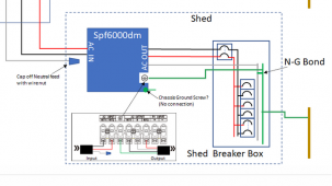
Ignore everything before the "Shed Breaker Box".

This was FilterGuy's reasoning:

View attachment 115628
3 N/G bonds and 2 separate connections to earth?
Is this what you are recommending?
Or just sharing how it should NOT be done.

A single N/G bond and ground rod, should both be at the pedestal box in that drawing. And nowhere else.
 
Last edited:
Ok, so in the potential above scenario, where and N/G bond is on grid panel (with L1, L2 and Ground connected to AC in) and on AC output (N/G bond at the shed panel), is that a “hesitant thumbs up for safety”, or is it still a no-no because of the double N/G bonded panels?

Also, is it only grid neutral imbalance that is a problem, or does inverter neutral imbalance then also a concern?
Two N/G bonds on one service is a human safety.

Transformer trying to balance the grid, is an equipment failure issue.

Human safety is always more important.
 
Back
Top